Table of Contents
Advertisement
Advertisement
Table of Contents

Related Manuals for Dirty Hand Tools 100983


Summary of Contents for Dirty Hand Tools 100983
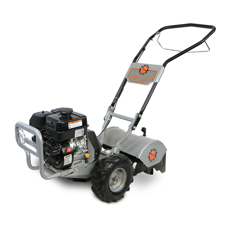
- Page 1 Counter-Rotating Rear Tine Tiller MODEL # 100983 Operation Manual This safety alert symbol identifies important safety messages in this manual. Failure to follow this important safety information may result in serious injury or death. Part # 101192 Rev D...
- Page 2 For Service or Questions Call 1-877-487-8275 720-287-5182 www.dirtyhandtools.com Dirty Hand Tools® is a brand of 1100 W 120th Ave, Suite 600 Westminster, CO 80234 • 720-287-5182...
-
Page 3: Table Of Contents
Table of Contents Important Safety Information Intended Use ................4 Personal Protective Equipment ..........4 General Safety ................5 Safety Decals ................6 Unpacking and Assembly Instructions Unpacking ...................7 Attaching the Handlebar .............8 Attaching the Wheels..............9 Tiller Overview .................10 Operating Precautions ..............11 Operating Instructions Preparation ................12 Pre-Start Inspection ..............12 Startup ..................13... -
Page 4: Important Safety Information
Important Safety Information WARNING WARNING: Read and thoroughly understand all instructions and safety information before assembling or operating this tiller. Failure to do so may cause serious injury or death. Do not allow anyone to operate this tiller who has not read this manual. As with all power equipment, a tiller can be dangerous if assembled or used improperly. -
Page 5: General Safety
Important Safety Information General Safety Failure to follow warnings, cautions, assembly and operation instructions in the Operation Manual may result in serious injury or death. DANGER READ THE OPERATION MANUAL BEFORE OPERATION. • Do not permit children to operate this equipment at any time. Do not permit others that have not read and understood the complete Operation Manual to operate this equipment. -
Page 6: Safety Decals
Safety labels on the tiller are to remind you of important information while you are operating the unit. Make sure all safety warning decals are attached and in readable condition. Replace missing or defaced decals. Contact Dirty Hand Tools at 1-877-487-8275 for replacement decals. DANGER... -
Page 7: Unpacking And Assembly Instructions
Unpacking and Assembly Your tiller comes partially assembled at the factory. The following instructions will help you unpack your tiller, assemble and adjust the depth regulator lever, cable tension and handlebar height. You will need 2- 9/16” wrenches. Unpacking Open top of carton and remove handlebar assembly. Find parts packet. -
Page 8: Attaching The Handlebar
1. Attaching the Handlebar 1. Place the handlebar plate on outside of upper handlebar assembly , align holes, and attach with Hex Bolts, M6 x 35 Hex Nuts, M6 Nylock in 4 places. 2. Position the upper handelbar assembly to align with one of the three sets of holes on the Tiller Frame and attach with Hex Bolt, M12 x 25... -
Page 9: Attaching The Wheels
2. Attaching the Wheels To place wheels in tilling position. (See Figure) 1. Slide wheel onto axle. 2. Align hole in axle with hole in wheel hub. 3. Insert lynch pin through holes, fold lock pin ring to secure pin. 4. -
Page 10: Tiller Overview
Tiller Overview SAFETY CONTROL LEVER DRIVE CABLE BELT GUARD DEPTH REGULATOR SAFETY SHIELD RECOIL STARTER WHEEL LOCK PIN... -
Page 11: Operating Precautions
Operating Precautions CAUTION READ, UNDERSTAND AND FOLLOW ALL OF THE PRECAUTIONS BELOW. Always perform the pre-start checklist before starting the engine. • Never operate the tiller without safety guards and covers in place. • Never start the engine or operate the tiller with the wheels in the free- wheel position. -
Page 12: Operating Instructions
Operating Instructions Preparation for Operation Fill Engine Crankcase with Oil 1. Add oil according to engine manual. Do not overfill. Use a clean, high quality detergent oil. Use no special additives with recommended oils. Do not mix oil with gasoline. Oil level must be full. -
Page 13: Startup
Operating Instructions WARNING NEVER START ENGINE OR OPERATE TILLER WITH WHEELS IN FREE-WHEEL POSITION. The free-wheel position is for transporting the tiller long distances. Start-Up The controls required to start and run the tiller are located on the engine and are marked “Choke” and “Throttle”. A detailed description of engine operation and precautions is available in the engine operation manual. -
Page 14: Tilling
Operating Instructions WARNING PRACTICE OPERATING THE CONTROLS AND USING THE TILLER WITH TINES OUT OF GROUND BEFORE Pulling the safety control lever towards the BEGINNING TO TILL. handlebar engages both It is important that you know how to use the tiller properly, the wheels and tines. -
Page 15: Depth Regulator Adjustment
Operating Instructions DEPTH Depth Regulator Adjustment REGULATOR LEVER Tilling depth is controlled by the height of the depth regulator lever. To adjust tilling depth (see Figure 3). DETENT 1. Remove detent pin. 2. Raise the depth regulator lever to position tines at chosen tilling depth. -
Page 16: Maintenance
Maintenance WARNING THE TILLER TRANSMISSION IS SHIPPED FROM FACTORY WITH THE CORRECT AMOUNT OF LIQUID GREASE. • Keep tiller, safety shields and covers, attachments, and accessories in safe working condition. • Check shear bolts, engine mounting bolts, and other bolts at frequent intervals for proper tightness to be sure the equipment is in safe working condition. -
Page 17: Belt Adjustment
Maintenance Belt Adjustment 1. Remove cover from rear of engine to expose belt. Check adjustment of belt guide rod. Rod should be just touching the belt (see Figure 5). 2. Run tiller in dirt and watch top drive pulley and belt for slipping. -
Page 18: Changing The Forward/Reverse Belt
Maintenance Changing the Forward/Reverse Belt 1. Turn off engine. Engine must be cool. 2. Remove spark plug wire and secure from spark plug. 3. Remove belt guard (see Figure 7). • Remove the forward belt from the forward engine pulley. •... -
Page 19: Engine Maintenance
Maintenance WARNING TURN OFF ENGINE AND DETACH SPARK PLUG WIRE. ENGINE MUST BE COOL. Engine Maintenance Refer to the engine manual included in your parts packet for information on engine maintenance. Your engine manual provides detailed information and a schedule for performing the following: 1. -
Page 20: Storage
Storage WARNING DO NOT STORE TILLER IN UNVENTILATED AREA where fuel fumes may reach flame, sparks, pilot lights or other ignition source. Drain fuel outdoors away from any ignition sources. Use only approved fuel containers. Prepare for Storage Follow the steps below to prepare your tiller for storage. Read your engine manual for detailed instructions on preparing the engine for storage. -
Page 21: Handlebar And Control Lever Parts List
Handlebar and Control Lever Parts List 4 Plcs 4 Plcs 2 Plcs Item # Part # Description Qty. 4 Plcs 100914 Control Lever 100913 Upper Handlebar Assembly 101728 Handlebar Plate 101713 Hex Bolt, M6 x 35mm 101494 Hex Nut, Nylock M6 100951 Cable Linkage 101907 Hex Nut, Nylock 10-24 100918 Compression Spring... -
Page 22: Motor Mount Parts List
Motor Mount Parts List... - Page 23 Motor Mount Parts List Item # Part # Description Qty. 101080 Tiller Frame Assembly 100972 Engine Assembly with Pulleys 100978 V-Belt, Transmission 100956 Belt Guide Rod 101719 Lower Belt Shield 100906 Engine Guard 100977 Gearbox Dip Stick 101180 Pulley Shield 101708 Button Head Bolt, M8 x 1.25 x 20mm 3 100129...
-
Page 24: Tines And Safety Shields Parts List
Tines and Safety Shields Parts List... - Page 25 Tines and Safety Shields Parts List Item # Part # Description Qty. 101104 Tine Cover Assembly 101715 Tine Guard Left 101716 Tine Guide Right 101714 Hex Bolt, M6 x 1.0 x 12mm, G8.8 100125 Hex Bolt, M8 x 1.25 x 20mm G8.8 101494 Hex Nut, Nylock, M6 x 1.0, G8.8 100128 Hex Nut, Nylock, M8 x 1.25, G8.8 100130 Flat Washer, M8...
-
Page 26: Troubleshooting
Troubleshooting PROBLEM SOLUTION • Add gas to gas tank. Engine will not start • Connect spark plug wire to spark plug • Throttle must be positioned at choke for a cold start Engine runs rough, floods during operation • Clean or replace air cleaner •... - Page 27 Notes...
-
Page 28: Warranty & Specifications
2 Year / 2 Year Limited Warranty *As rated by engine manufacturer ** Not included, shipped without engine oil For Service or Questions Dirty Hand Tools® is a brand of Call 1-877-487-8275 720-287-5182 1100 W 120th Ave., Suite 600 www.dirtyhandtools.com...
Need help?
Do you have a question about the 100983 and is the answer not in the manual?
Questions and answers
What kind of grease does the transmission take
The recommended grease for the Dirty Hand Tools transmission with part number 100983 is Mobilux EP1 or an equivalent transmission grease.
This answer is automatically generated
@Mr. Anderson V Belt size for 100983
What size is the V belt?