
Related Manuals for SurgeX SEQ-1U

Summary of Contents for SurgeX SEQ-1U
- Page 1 SEQ / SEQ-1U Programmable Sequencer/ Surge Eliminator/Power Conditioner User Manual Software Version: 2.0 © SurgeX | Technical Support: 800-645-9721 | surgex.com...
- Page 2 SEQ/SEQ-1U User Manual Software Version 2.0 © SurgeX | Technical Support: 800-645-9721 | surgex.com Page 2...
-
Page 3: Table Of Contents
6.1.1 Controlling the SEQ 6.1.2 12V DC Output 6.1.3 Auxiliary Relay 6.1.4 Over-ride Function 6.1.5 Other Functions Single Unit Systems Expanded System Ganged System Cascaded System Troubleshooting Error Codes Specifications © SurgeX | Technical Support: 800-645-9721 | surgex.com Page 3... -
Page 4: Introduction
The SEQ is microprocessor controlled and designed to be versatile and expandable. Two or more SEQs can be connected together to provide control and power conditioning for larger systems. The SEQ can also control other SurgeX products with its auxiliary relay contacts and/or its 12V dc output. All options are set via the front panel and all connections are made at the rear panel. -
Page 5: Features
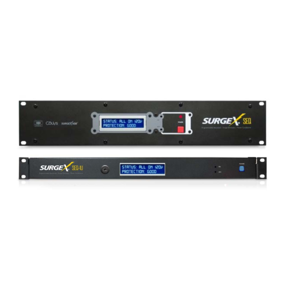
The SEQ-1U is designed to be installed in a 19 inch equipment rack and requires one unit (1RU) of rack space. Use the eleven flathead screws (included) to secure the left and right rack ears to the product. Use the four thumbscrews (included) to secure the rack ears to the rack rails. -
Page 6: Remote Control Connections
Connect the two wires from the switch to “Up” and “Common”. Program the input for “Latching”. Note: The front panel button will not operate with options a, b or f © SurgeX | Technical Support: 800-645-9721 | surgex.com Page 6... -
Page 7: Over-Ride Input
The default for menu item “Aux Output” is “Confirm” so you do not need to program this item unless you previously changed it. The contacts are rated for 30V DC at 1 Amp. © SurgeX | Technical Support: 800-645-9721 | surgex.com Page 7... -
Page 8: Quick Start
Shuts unit off if AC voltage rises above the set point Self-Test Shutdown Shuts down unit if self-test fails Turns unit back on after a power failure if unit was powered up when the power Power Fail Restore failed © SurgeX | Technical Support: 800-645-9721 | surgex.com Page 8... -
Page 9: Programming
Delay A, B, C On 1 – 40 Set power-up delay time for each bank Seconds Delay A, B, C Off 1 – 40 Set power-down delay time for each bank Seconds © SurgeX | Technical Support: 800-645-9721 | surgex.com Page 9... -
Page 10: Over-Ride Control
Note that the push button cannot be used in conjunction with applied voltage or latching type remote control inputs. Menu Item Options Description Front Panel Enable Front panel button is enabled Button Delay Button has a 1 second delay Disable Front panel button is disabled © SurgeX | Technical Support: 800-645-9721 | surgex.com Page 10... -
Page 11: Dc Output
Main Bank C Off (the 12V Delay Off can be set to zero in this case). © SurgeX | Technical Support: 800-645-9721 | surgex.com Page 11... -
Page 12: Auxiliary Relay
Options Description Low Volt Shut Down 90 – 110 VAC Set low voltage shut down point High Volt Shut Down 130 – 150 VAC Set high voltage shut down point © SurgeX | Technical Support: 800-645-9721 | surgex.com Page 12... -
Page 13: Self-Test Failure Shut Down
Menu Item Options Description Password A - Z Set optional password of up to six letters. Set each letter with ADJ and advance SEL to go to the next letter. © SurgeX | Technical Support: 800-645-9721 | surgex.com Page 13... -
Page 14: Applications
The SEQ can be used in four types of configuration: a single unit providing three sequenced banks; an expanded system where the SEQ controls remote turn-on SurgeX products providing four or five sequenced banks (or three banks with increased current capacity on extra units); a ganged system where two or more SEQs are connected together such that they all turn on and off at the same time providing three banks with increased current capacity for all three banks;... -
Page 15: Auxiliary Relay
The SEQ has built-in voltage limits that will cause the unit to power down if the line voltage is outside these limits. The low limit can be set from 90V to 110V and the high limit can be set from 130V to 150V. See Section 5.6 for more details. © SurgeX | Technical Support: 800-645-9721 | surgex.com Page 15... -
Page 16: Single Unit Systems
Most of the information necessary to install and set up a single unit system can be found in Sections 3.2 and 6.1. Figure 1 shows a single unit system controlled by momentary switches at three different locations, and Figure 2 shows a single unit controlled by a central controller. © SurgeX | Technical Support: 800-645-9721 | surgex.com Page 16... -
Page 17: Expanded System
Expanded System A basic expanded system consists of an SEQ in combination with a remote turn-on SurgeX such as the SX1120- RT or the SX20-NE/RT. Such a system provides a total of four banks and 40 Amps total load capacity. The auxiliary relay inside the SEQ is normally used to control the second unit although the 12V DC output can also be used for this purpose. - Page 18 The aux output and the 12V DC output could be programmed to be the first two sequenced banks, or the last two sequenced banks. Similarly, the rack-mount SX1120RT remote turn-on SurgeX was used in this example whereas the ICE20C or the hard-wired SX20-NE/RT could equally have been used.
- Page 19 SEQ/SEQ-1U User Manual Software Version 2.0 © SurgeX | Technical Support: 800-645-9721 | surgex.com Page 19...
-
Page 20: Ganged System
The other units should be left set to 90V and 150V.The two restore options should only be enabled (if required) on the first unit. The self-test shutdown should be the same for all units. If an over-ride is required connect it to the first unit. © SurgeX | Technical Support: 800-645-9721 | surgex.com Page 20... -
Page 21: Cascaded System
(if required) on the first unit. The self-test shutdown should be the same for all units. If an over-ride is required connect it to the last unit and program that unit to accept the type of over-ride you need. © SurgeX | Technical Support: 800-645-9721 | surgex.com Page 21... -
Page 22: Troubleshooting
If Error 15 is still displayed there is most likely a permanent problem with the non- volatile memory. Error 16 There is an internal error. The unit will need to be returned to the factory for repair. Error 24 Please call the factory. © SurgeX | Technical Support: 800-645-9721 | surgex.com Page 22... -
Page 23: Specifications
* 1.2 x 50 microsecond industry standard combination wave surge as per IEEE C62.41 *CAUTION: Do not install this device if there is not at least 10 meters (30 feet) or more between the electrical outlet and the electrical service panel. © SurgeX | Technical Support: 800-645-9721 | surgex.com Page 23...
Need help?
Do you have a question about the SEQ-1U and is the answer not in the manual?
Questions and answers