Advertisement
308 Industrial Park Road
Starkville, MS 39759 USA
Ph: (662) 323-9538 FAX: (662) 323-6551
INSTRUCTION MANUAL
GENERAL DESCRIPTION
The HAM IV rotator consists of a bell type
rotator, a metered control unit and the necessary
mounting hardware. The stock HAM IV is
intended for in-tower mounting on the base plate
which is part of the tower. However, in some
instances, mast mounting is desired. The Lower
Mast Support Kit, PN 51467 10, contains a lower
mast support and the necessary hardware to
facilitate mounting the HAM IV Rotator on top
a
of
mast.
New features in the HAM IV include an 8 pin
Cinch connector on the rear panel of the control,
a chassis ground connection on the 110 VAC
model, and a locking CinchTM connector at the
rotor unit.
CAUTION
When using the lower mast support, antenna
size is restricted to 7.5 square feet of wind
surface area
Cinch'm a Division of Labinal Components & Systems,
HAM IV / HAM IVX
HAM IV has 110 VAC
Controller HAM IVX has 220
The rotator unit must be wired to the control unit
with an 8-wire cable. The control unit must be
placed inside the house or other protected
location. Included in the shipping box are:
A. Instruction Manual
B. Rotator Unit
C. Controller Unit
D. Mounting Hardware Pack
E. Connector Parts Pack
Due to the wide variety of towers available, each
installation will have different requirements. The
gauge of the 8-wire cable to connect the control
unit to the rotator depends upon the distance
between the rotator and control. The longer the
distance, the larger the diameter of the wire
required. Various antennas or beams require
different installation methods.
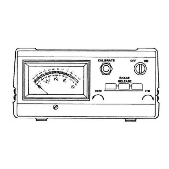
Figure 1
Control Unit - Front Panel
Antenna Rotator
Advertisement
Table of Contents

Related Manuals for Hy-Gain HAM IV

Summary of Contents for Hy-Gain HAM IV
- Page 1 HAM IV Rotator on top C. Controller Unit mast. New features in the HAM IV include an 8 pin D. Mounting Hardware Pack Cinch connector on the rear panel of the control, E. Connector Parts Pack...
- Page 2 Specifications Input Voltage 120 VAC 50/60 Hz Optional 220 VAC 50/60 Hz Motor 24 VAC 2.25 Amp, capacitor start, capacitor run Brake Solenoid 24 VAC, 5.0 Amps Power Transformer 120 VAC/26 VAC 10% duty, thermal switch protected Optional 220 VAC/26 VAC 10% duty, thermal switch protected Meter Transformer 120 VAC/23 VAC continuous duty Optional...
-
Page 3: Types Of Installation
• Read this manual completely before proceeding. The HAM IV rotator has been carefully designed and manufactured to give many years of trouble-free service when carefully and professionally installed. It consists of the strongest and best commercially available components. - Page 4 D. With the rotator sitting in the upright position WIRING AND CHECK-OUT and connected to the control unit by the 8- A. Decide the wire gauge (size) required and wire cable, plug the control unit power cord procure the number of feet of the proper cable into a receptacle.
- Page 5 ROTATOR UNIT CONNECTOR MOUTING INSIDE TOWER The Ham IV is now supplied with an 8 pin The rotator is mounted inside a tower (see Figure Cinch® connector with lock. This connector is 4) to the flat tower plate by means of four (4) not waterproof and requires a heatshrink "boot"...
- Page 6 NOTE: Apply a coating of heavy-duty motor oil 3. The rotator is attached to the tower plate by or grease to the threads of the stainless steel bolts means of four (4) bolts and lockwashers (see and U-bolts to prevent seizing. Figure 4).
- Page 7 Figure 5 Rotator Mounted on Tower Top Plate Figure 6 Pole Mounted Rotator...
-
Page 8: Optional Kits
The four (4) bolts must be torqued to support and the necessary hardware to facilitate the same specification and the 8-wire cable mounting the HAM IV on top of a tower stub or securely fastened. The lower mast should be mast. -
Page 9: Normal Operation
PRELIMINARY CHECK AND NORMAL OPERATION CALIBRATION To operate the rotator, it is necessary to understand the HAM IV Brake Release Lever and its function. The brake lever (middle lever) IMPORTANT on the Control Unit operates a brake wedge THERMAL PROTECTION: If the rotator... - Page 10 Make sure the CONVERSION scale fits over the indexing pins and that it is The stock HAM IV Control Unit is shipped with flush and tight against the black housing. the meter scale installed for "North" center This will assure free movement of the operation;...
-
Page 11: Troubleshooting
LACK OF POWER TROUBLESHOOTING If the antenna rotation is slow or sluggish or hard to start, check for proper voltages. If the voltages CAUTION are correct, the 130-156 mfd motor start capacitor could be at fault. It is recommended that a new This unit has been thoroughly tested and capacitor be tried before any other action is cycled before shipment. - Page 12 NO ROTATION - INDICATION OK 2. Resistances with Unit Not Plugged In. Either the thermal cut-out in the power Disconnect the AC power source and discon- transformer has opened or there is actually nect the 8-wire control cable. Be sure to tag trouble in the motor circuit.
- Page 13 ADDITIONAL CHECKLIST Be sure cable is of proper size for length used. Refer to Table 1. l. Check continuity of control wires for loose connections caused by wind. 8. Substitute a 3 foot piece of new rotator cable to bench test unit. Proper operation will 2.
-
Page 14: Parts List
Flatwasher, 1/4" ..........:...........2 556960 Nut, Hex, 1/4"-20..................1 550029 Nut, Wing, 1/4"-20..................1 710083 Holder, Bulb....................1 567125 Lockwasher, #10 Internal................4 Hy-Gain reserves the right to change prices at its option. Current prices may be obtained by calling or writing the factory. - Page 15 Figure 9 Wiring Schematic Figure 10 Control Unit - Front Panel...
- Page 16 Figure 11 Control Unit - Top View Figure 12 Control Unit - Back View...
- Page 17 HAM IV Rotator Replacement Parts ITEM PART DESCRIPTION QTY 878712 Rotator (complete with hardware) ..............1 5030400 Support, Upper Mast (bell casting) .............1 5136502 Brake Housing (lower casting) ..............1 5033501 Bearings, Ball (49 per retainer)..............98 5011300 Retainer, Bearing (one per race) ..............2 5136101 Gear, Steel Drive..................1...
- Page 18 Figure 13 Inside View of HAM IV Rotator...
- Page 19 This information is believed correct, but no warranty is given or implied and no liability is assumed by Hy-Gain as to its accuracy or completeness. Changes may be made from time to time so the user should verify all factors that may be critical. This information is not to be...
-
Page 20: Limited Warranty
Hy-Gain Warrants to the original owner of this product, if manufactured by Hy-Gain and purchased from an authorized dealer or directly from Hy-Gain to be free from defects in material and workmanship for a period of 12 months for rotator products and 24 months for antenna products from date of purchase provided the following terms of this warranty are satisfied.
Need help?
Do you have a question about the HAM IV and is the answer not in the manual?
Questions and answers