
Subscribe to Our Youtube Channel
Related Manuals for Firecom WB505L

Summary of Contents for Firecom WB505L
- Page 1 WB505R / WB505L Wireless DECT7 Base Station Manual 7340 SW Durham Road, Portland, OR 97224 USA Phone: 800-527-0555, 503-684-6647, Fax 503-620-2943 www.firecom.com • e-mail: service@firecom.com...
-
Page 3: Table Of Contents
Setting up Digital Intercom Mode (WB505R default) .......... 11 Digital Intercom Radio Transmit ................11 Intercom Only ...................... 11 Base Station connected to a Firecom Digital Intercom ........12 Use with a Legacy Intercom – WB505L ..............13 Setting up Legacy Intercom Mode (WB505L default) .......... 13 Intercom Connections .................. -
Page 4: Overview
Overview Firecom Wireless Base Stations support the RF connections of Firecom wireless communication systems. The Base Station supports full duplex, conference call like digital communication for up to five Firecom DECT7 Wireless Headsets. Radio PTT capable Headsets can be set up to transmit on a mobile radio via a Firecom Digital Intercom. -
Page 5: Contents In Box
Contents in Box Base Station 1 ea x Wireless Base Station Antenna 1 ea x Duck Antenna 1 ea x Duck Antenna Mount 1 ea x Wire Tie Manual and Reference 1 ea x Manual 1 ea x FCC/IC certification sheet 1 ea x ComCare sheet Power 1 ea x DC Power Cable... -
Page 6: Features
The Base Station features wireless DECT7, enabling conference call-like full duplex communication. The Firecom wireless DECT7 Base Station will connect with Firecom Wireless Headsets and Belt Packs. DECT7 networks have up to 1600ft line-of-sight range in Region 1 (US) and up to 800 meters in Region 2 (EU). -
Page 7: Mounting
Mounting The Wireless Base Station is designed to mount on a variety of surfaces. The unit includes internal and external antennas. Consideration must be given to antenna location to optimize performance. WARNING: Do not locate the Wireless Base Station within 4” of any metal. -
Page 8: Antennas
Antennas An external antenna can provide a performance increase in some locations, and affords greater installation flexibility. To optimize performance: 1. Position the antenna at least 12 inches from any other antenna, metal, electrical power, radio equipment, or obstructions. 2. Choose a location in the center of the vehicle’s roof (if mounting outside). -
Page 9: Accessory Antennas
Accessory Antennas Sonetics has accessory antennas for temporary and permanent installation on the exterior of a vehicle or building. To ensure the best system performance, external antennas must not be mounted inside metal enclosures. Magnet Mount Antenna This antenna is designed for non-permanent installations on metallic surfaces. Temporarily mark the center of the vehicle’s roof or trunk. -
Page 10: Power
Power The Wireless Base Station can be powered from the DC Jack or directly from a Digital intercom. The unit will automatically power on when power is applied. WARNING: Use only one power option to prevent ground loops. Option 1: DC Jack Power Wall Adapter Charging Only charge the base station using the supplied 12VDC regulated wall adapter. -
Page 11: Option 2: Digital Intercom Power
Option 2: Digital Intercom Power Connect one RJ-45 modular plug as shown above. Both the Power and Ground will be connected from the Digital Intercom to the Wireless Base Station. Any input will power the Wireless Base Station. Adjust the fuse of the Digital Intercom to include the current draw from the Wireless Base Station. -
Page 12: Modular Plug Installation
Modular Plug Installation Using the cutter blade on the crimping tool (A), cut the flat CA Cable so the cut is clean and 90 degrees to the sides of the cable. Insert one end of the CA Cable between the stripping blades (C) until the end of the cable hits the stop (B). -
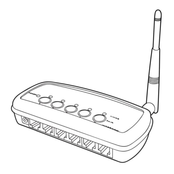
Page 13: Led Indicators
LED Indicators Power Indicator Lights when unit has power and is turned on. Link Indicators There is one light per wireless position. These indicate the connection status of the wireless devices paired onto the Wireless Base. Off – No wireless device is paired to this position Slow Flashing –... -
Page 14: Use With A Digital Intercom - Wb505R
Some models of Wireless Headsets have radio transmit capability built in. Headsets can receive and transmit via the built in PTT button. The Wireless Base Station must be connected to a Firecom intercom that is connected to a two-way-radio. Consult your Intercom manual for instructions on how to connect them. -
Page 15: Base Station Connected To A Firecom Digital Intercom
Base Station connected to a Firecom Digital Intercom Examples: Stand Alone, No Radio Interface All positions communicate locally via the Base Station only. With no connection to a Digital Intercom, the headsets will only be able to communicate with other headsets connected to the Wireless Base Station. -
Page 16: Use With A Legacy Intercom - Wb505L
In this mode, the position a Headset is paired to does not impact its operation. Intercom Connections In this mode port 6 must be connected to a Firecom Intercom using the supplied flat cable. Pair the Headset(s) to the Base Station. For Radio Transmit operation, make sure your Headset is a radio transmit model and that it is configured to transmit radio over DECT. -
Page 17: Base Station Connected To A Firecom Legacy Intercom
Base Station connected to a Firecom Legacy Intercom Examples: Intercom Only Connected to Digital Intercom The Intercom port only is connected. All paired devices will only transmit over the Intercom. No intercom radio transmit is available. Make sure all headsets are set to intercom only modes. -
Page 18: Use In A Comhub
Use in a Comhub In addition to being used in an installed system, your Base Station can be used in a portable Comhub. Up to 5 channels are available through the Wireless Base Station when used in this configuration. Setting up Comhub mode, and the number of channels To enter configuration mode: Unplug the Base Station, then plug it back in while holding the position 3 pairing button. -
Page 19: Pairing
Press and hold the desired pairing button until its link indicator begins to flash slowly. Any previous pairing to that position will be forgotten. Place the Firecom headset into pairing mode by pressing the right PTT button and the power button until you hear "base station registering". -
Page 20: Pc Programming
To exit Broadcast Only mode: Press and hold 4 or 5 until the link LED flashes slowly indicating pairing mode. PC Programming The Wireless Base Station has a USB port located near the Antenna Jack. Using the Sonetics Configurator software, you can adjust additional features using a Windows PC. -
Page 21: Troubleshooting
4 inches to a metal object or surface. Poor range can also be caused by a defective Headset. Check operation with a known, properly functioning Headset. If the problem persists, contact Firecom Service for additional help. 18 | P a g e... -
Page 22: Wb505R / Wb505L Specifications
WB505R / WB505L Specifications Physical Length: 5.70in / 145mm Width: 2.72in / 69mm (not including external antenna) Height: 1.22in / 31mm Weight: 5.6oz / 158g Power Voltage Input: 5 VDC to 16 VDC Maximum Current Input: 400mA @ 5V, 150mA @ 12V... -
Page 23: Dect Specifications
DECT Specifications Common DECT Specifications Carrier Spacing: 1.724 MHz Time Slots: 2 x 12 (up and down stream) Channel Allocation: Dynamic Encryption: DECT Standard Cipher with 35-bit initialization vector Audio Bandwidth: 300 Hz to 3.4 kHz, Narrow Band, G.726 compression 50 Hz to 7 kHz, Wide Band, G.722 compression Region 1 Specific Specifications Authorized for use in:... -
Page 24: Important Safety Information
Important Safety Information CAUTION! Follow all warnings and instructions marked on the product or contained in the owner’s manual. When using this product, always follow basic safety precautions to reduce the risk of fire, electric shock and injury to persons, including the following: Do not use the wireless system to report a gas leak in the vicinity of the leak. - Page 25 Approved Antennas for use with this device: WB505R / WB505L Wireless Base Station Antenna Sonetics Part Number: 521-0014-00 (3dBi) Magnet Vehicle Mount Sonetics Part Number: 114-0139-00 (4.4dBi) (Sold Separately)
- Page 26 This section applies to radio frequency Ce dispositif est conforme à la norme equipment bearing an I.C. equipment CNR d'Industrie Canada applicable aux ID number. appareils radio exempts de licence. This device complies with Industry Son fonctionnement est sujet aux Canada license-exempt RSS deux conditions suivantes: standard(s).
- Page 27 FCC Part 15 Information This device complies with part 15 of the FCC rules. Operation is subject to the following two conditions: (1) This device may not cause harmful interference, and (2) This device must accept any interference received, including interference that may cause undesired operation.
- Page 28 FCC Authorized Antenna Information: Under FCC regulations, this radio transmitter may only operate using an antenna of a type and maximum (or lesser) gain approved for the transmitter by FCC. To reduce potential radio interference to other users, the antenna type and its gain should be so chosen that the equivalent isotropically radiated power (e.i.r.p.) is not more than that necessary for successful communication.
-
Page 29: Firecom Standard Limited Warranty
Firecom; (e) to damage caused by service performed by anyone who is not a representative of Firecom or an Firecom Authorized Service Provider; (f) to a product or part that has been modified without the written permission of Firecom;... - Page 30 Page intentionally left blank. 27 | P a g e...
- Page 32 Firecom, a division of SONETICS CORPORATION Copyright ©2015 Sonetics Corporation - All rights reserved. The information in this document is subject to change without notice. P/N: 600-0386-00 Rev. E...
Need help?
Do you have a question about the WB505L and is the answer not in the manual?
Questions and answers