Table of Contents
Advertisement
Quick Links
Advertisement
Chapters
Table of Contents

Summary of Contents for Gen Set MG 8000 I-H
- Page 1 MG 8000 I-H MANUAL NUMBER MI-G-00005700 REVISION LEVEL 0 29-09-2008 GENERATING SET USE AND MAINTENANCE MANUAL GEN SET S.p.a. Via Stazione,5 - 27030 Villanova D’Ardenghi (Pavia) Italy Tel. (+39) 0382-5091 - Fax (+39) 0382-509-244 E-mail: genset@genset.it - internet: //www.genset.it...
- Page 2 It is recommended to read this manual thoroughly because incorrect operation may result in the warranty being void. Therefore it is also recommended to use only original Gen Set S.p.A. spare parts. Reproduction of this manual is not permitted, unless written approval is obtained from...
- Page 3 06. INSTALLING AND STARTING THE POWER GENERATOR page 23 07. USING THE GENERATOR page 26 08. MOVING THE GENERATOR page 30 09. GENERATOR MAINTENANCE page 33 10. SPARE PARTS page 39 11. ELECTRICAL DIAGRAM page 46 12. ATTACHMENTS page 48 MG 8000 I-H MI-G-00005700...
-
Page 4: Table Of Contents
01. REFERENCE GUIDE 01.1- This publication........................page.5 01.2- Purpose..........................page.5 01.3- Reference to regulations......................page.5 01.4- Using this manual........................page.6 01.5- Terminology..........................page.6 01.6- Abbreviations........................page.6 MG 8000 I-H MI-G-00005700... -
Page 5: This Publication
The “USE AND MAINTENANCE MANUAL”, published Its value changes with the distance from the source and is by the manufacturer, GEN SET S.p.A., is an integral part also measured in dB(A). of the power generator. The manual is identified by a... -
Page 6: Using This Manual
: referred to an operator standing in RIGHT OR LEFT SIDE front of the unit and looking at the control panel. second °C degree Celsius sound power level sound pressure dB(A) decibel collegamento a stella collegamento a triangolo MG 8000 I-H MI-G-00005700... - Page 7 02. ACCIDENT PREVENTION / SAFETY REGULATIONS 02.1- Precautions to be observed....................page.8 02.2- Risks for the operator when using this unit................page.9 02.3- Protective clothing recommended for operators..............page.9 02.4- Meaning of safety signs......................page.10 02.5- Location of safety signs provided on the unit................page.13 MG 8000 I-H MI-G-00005700...
- Page 8 • Use fume extractors to ensure the correct air turnover when operating indoors. • Do not operate near flammable materials. • Fill fuel tank when engine is stopped. Do not smoke when fuelling. • Do not overfill the tank and clean up any spilled fuel. MG 8000 I-H MI-G-00005700...
- Page 9 • Install and maintain equipment according to regulations. • Protective ear plugs and/or earmuffs • Switch off the generator and disconnect the battery before performing any service or repairs. N.B.: material not supplied. • Read and follow all the instructions in this Manual. MG 8000 I-H MI-G-00005700...
- Page 10 Danger of electric discharges: read the manual. MG 8000 I-H MI-G-00005700...
- Page 11 Prohibition of cleaning, lubricating, repairing or adjusting moving parts. Prohibition of extinguishing fires with water; use fire extinguishers containing proper extinguishing agents. Prohibition of using flames or smoking. MG 8000 I-H MI-G-00005700...
- Page 12 This card warns that the battery that the has no acid. Before starting the generator, prepare the battery according to the instructions of Chapter "06". Marks the position of the points for lifting the unit using a fork lift. MG 8000 I-H MI-G-00005700...
- Page 13 02.5 LOCATION OF SAFETY SIGNS PROVIDED ON THE UNIT TOP VIEW Circuit Breakers Circuit Breakers Circuit Breakers Circuit Breakers MG 8000 I-H FRONT VIEW 240V AC 120V AC Cosf GENE RATO R SET IS DESIGNE D TO O PERATE IN A MB IEN T TEMPERAT URES UP TO 40°...
- Page 14 03. ENVIRONMENTAL DIRECTIONS 03.1- Waste material and lubricating oil..................page.15 03.2- Disposal of the unit......................page.15 MG 8000 I-H MI-G-00005700...
- Page 15 Do not dispose of any type of lubricating oil, mineral or synthetic, onto land,drains or sewers. Dispose of batteries as instructed by local legislation. MG 8000 I-H MI-G-00005700...
- Page 16 04. THE POWER GENERATOR 04.1- Generator components......................page.17 04.2- Control panel description.....................page.18 MG 8000 I-H MI-G-00005700...
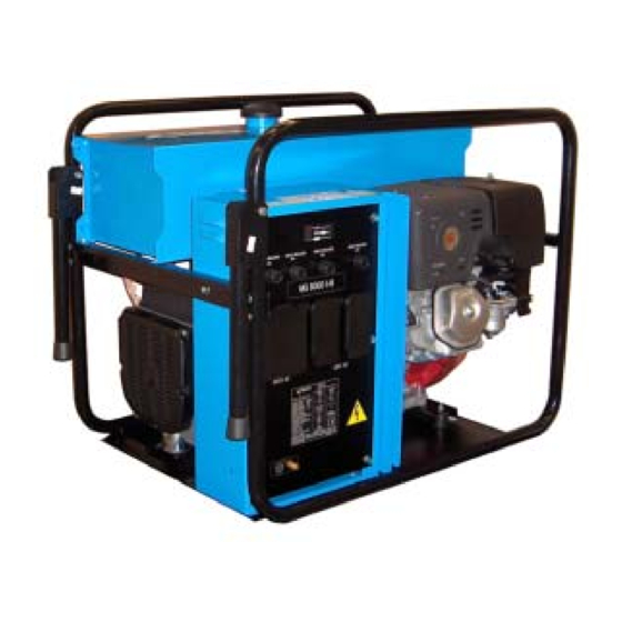
- Page 17 04. THE POWER GENERATOR 04.1 GENERATOR COMPONENTS Right side front view Fuel filler cap Frame Fuel tank Control panel Muffler Recoil starter Air cleaner Starter grip Left side rear view Electric starter Oil drain plug Alternator Oil filler cap/dipstick MG 8000 I-H MI-G-00005700...
- Page 18 Circuit Breakers Circuit Breakers 5. 120 V 2x15 A socket 6. Data plate 7. Earth clamp MG 8000 I-H 240V AC 120V AC Cosf GENERATOR SET IS DESIGNED TO OPER ATE IN AMBIENT T EMPER ATURES UP T O 40°C AND 1000 MT ALTIT UDE −...
- Page 19 05. TECHNICAL DATA 05.1- Generator..........................page.20 05.2- Engine..........................page.20 05.3- General specifications......................page.20 05.4- Rating plate description......................page.21 05.5- Outline dimensions.......................page.22 MG 8000 I-H MI-G-00005700...
-
Page 20: Generator
Noise power emission level Fuel tank capacity 30 l Operating range at 75% of continuous service power 10 h 30 min. ~ Weight 91 Kg Dimensions (L x W x H) 727 x 525 x 606 MG 8000 I-H MI-G-00005700... -
Page 21: Rating Plate Description
5. Unit’s degree of protection 6. Insulation class 7. Ambient temperature 8. Altitude reference 9. Engine speed 10. Unit’s serial number 11. Year of manufacture 12. EC Marking 13. Machine weight 14. Noise power emission level (Lwa) MG 8000 I-H MI-G-00005700... -
Page 22: Outline Dimensions
T E MPE R A T UR E S A N D A L T IT UD E S PL E A SE C O N SU LT F A C T O R Y T O C H E C K A VA ILA BL E P O WE R IS O 85 28 1035 Trolley-mounted unit (dimensions in mm) MG 8000 I-H MI-G-00005700... - Page 23 06. INSTALLING AND STARTING THE POWER GENERATOR 06.1-Preliminary operations......................page 24 06.2-Maximum operating angles....................page 25 06.3-Location..........................page 25 06.4-Checking generator operation....................page 25 06.5-Generator unit run-in......................page 25 MG 8000 I-H MI-G-00005700...
- Page 24 • When filling up always use the fuel filter. • Carefully clean up any trace of fuel that came out before starting the motor. MG 8000 I-H MI-G-00005700...
- Page 25 70% of the maximum power output rated in 10° the technical specifications. After first 20 hours of operation change the engine oil. MG 8000 I-H MI-G-00005700...
- Page 26 27 07.2- Starting the engine.......................page 27 07.3- Using the power generator unit....................page 28 07.4- Stopping the engine......................page 28 07.5- Adjustments and settings.....................page 29 07.6- Putting the power generator temporarily out of service and restarting operation......page 29 MG 8000 I-H MI-G-00005700...
-
Page 27: Earthing The Power Generator
- At those times when it is not necessary to run the motor at a high speed, put the speed control lever at a minimum in order to save fuel and extend the life of the motor itself. MG 8000 I-H MI-G-00005700... -
Page 28: Using The Power Generator Unit
For operations involving the electrics contact only an authorised Gen Set centre. • Before connecting a load to the grip at the front of the machine make sure that the generator is providing sufficient power for the tools that are being connected. -
Page 29: Adjustments And Settings
When putting the generator back to service, all fluids should be replaced, the battery should be charged, engine belts, if any, all couplings and fuel pipes and seals should be checked. In case of longer out of service periods, contact Gen Set Service Department. MG 8000 I-H... - Page 30 08. MOVING THE GENERATOR 08.1- Packing, transporting and storing the unit................page 31 08.2- Lifting and moving the unit....................page 32 MG 8000 I-H MI-G-00005700...
- Page 31 THE UNIT Packaging The package is provided by Gen Set S.p.A.. C i r c u i t B r e a k e r s 4 0 A C i r c u i t B r e a k e r s...
- Page 32 Lay the generator on the ground gently. When lifting and moving the generator, do not stay or walk within it’s proximity. Never leave the generator slung overhead (picture 4). When moving and transporting the generator, do not tilt it excessively. MG 8000 I-H MI-G-00005700...
- Page 33 09. GENERATOR MAINTENANCE 09.1- Maintenance........................page 34 MG 8000 I-H MI-G-00005700...
- Page 34 Elimination of the coal residual of the head of the cylinder Cleaning and regulation of the carburetor General review of the engine, if necessary If the generator works in adverse conditions, the intervals between maintenance schedules must be reduced. MG 8000 I-H MI-G-00005700...
- Page 35 The Oil Alert system will automatically stop pic.2 the motor before the oil drops below the safety limit. Nevertheless, to avoid the nuisance of an unexpected shutdown, always check the oil level of the motor before starting it. MG 8000 I-H MI-G-00005700...
- Page 36 Once five minutes have passed check the level of the oil using the dipstick. It is important that the machine is perfectly level. The specified maximum level (picture 2, page 35) should never be exceeded. MG 8000 I-H MI-G-00005700...
- Page 37 • After removing the water of dirt wash the plug with gasoline. When putting it back tighten it well to avoid leaks later. The use of open flames is prohibited. MG 8000 I-H MI-G-00005700...
- Page 38 • Only then, after the machine has been switched off, reconnect the capacitor to the alternator. Unplanned maintenance Apply only to authorised Gen Set centres for any unplanned service operations related to electrical components. Apply to service centres authorised by the manufacturer of the engine for any problems related to the engine (page 39).
- Page 39 10. SPARE PARTS 10.1- Spare part codes........................page 40 MG 8000 I-H MI-G-00005700...
- Page 40 42109 42573 42132 42397 42108 42110 RATING PLATE SPARE PART CODE STOP 42111 138250 42112 GX 390 OHV HONDA ENGINE 42119 COMPONENTS SPARE PART CODE Air filter 17210ZE3505 42114 Fuel filter 16955ZE1000 Spark plug 98079-56846 42116 MG 8000 I-H MI-G-00005700...
- Page 41 10. SPARE PARTS List of spare part codes o o o o o N N N N N ..MG 8000 I-H MI-G-00005700...
- Page 42 10. SPARE PARTS MG 8000 I-H MI-G-00005700...
- Page 43 10. SPARE PARTS List of spare part codes o o o o o N N N N N ..l l i MG 8000 I-H MI-G-00005700...
- Page 44 10. SPARE PARTS BOTTOM VIEW MG 8000 I-H MI-G-00005700...
- Page 45 10. SPARE PARTS List of spare part codes o o o o o N N N N N ..t i l MG 8000 I-H MI-G-00005700...
- Page 46 11. ELECTRICAL DIAGRAM 11.1- Electrical diagram......................page 47 MG 8000 I-H MI-G-00005700...
- Page 47 11. ELECTRICAL DIAGRAM 11.1 ELECTRICAL DIAGRAM STATOR ROTOR CAPACITOR CONTROL PANEL Pt: 20A Pt1: 40A 120V MG 8000 I-H MI-G-00005700...
- Page 48 12. ATTACHMENTS 12.1- Authorised service centre......................page 49 12.2- List of documents........................page 50 12.3- Statement of warranty......................page 50 MG 8000 I-H MI-G-00005700...
- Page 49 12. ATTACHMENTS 12.1 AUTHORISED SERVICE CENTRE SERVICE: MASE GENERATORS OF NORTH AMERICA masegen@masenorthamerica.com E-MAIL: ADDRESS: 3750 HACIENDA BOULEVARD SUITE E LOCALITY: FL 33314 DAVIE (USA) FOR SERVICE OR REPAIR, PLEASE CONTACT PHONE NUMBER: +1/954/3270234 MG 8000 I-H MI-G-00005700...
- Page 50 • Warranty card. 12.3 STATEMENT OF WARRANTY GEN SET S.p.A. warrants its products, on condition that they are not altered, for a period of 12 (twelve) months beginning on the date of sale to the first user. Within this time period, in the countries where a service organisation is established, GEN SET S.p.A. undertakes to replace or repair the defective parts because of material defects, workmanship and/or assembly by means of its own AUTHORISED WOKSHOPS.
Need help?
Do you have a question about the MG 8000 I-H and is the answer not in the manual?
Questions and answers