
Subscribe to Our Youtube Channel
Summary of Contents for BriarTek Orca DF-101
- Page 1 ORCA DF-101 IS AN IDENTIFICATION AND RECOVERY SYSTEM FOR NAVY FLEETS DF-101 User Manual and Installation Guide...
- Page 2 BriarTek, Inc. Technical Support: (703) 548-7892 Email: support@briartek.com Web: www.briartek.com...
-
Page 3: Table Of Contents
Table of Contents DF-101 Introduction ................ 5 DF-101 Parts Overview ..............5 DF-101 Functions ................6 Power On/Off ................... 6 Speaker ..................6 Clear ....................6 Squelch ..................6 Dim ....................7 Signal Strength ................7 Warning ..................7 Default Settings ................7 Installation Notes ................ -
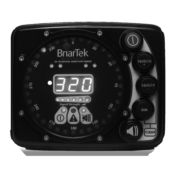
Page 4: Df-101 Introduction
DF-101 Introduction The DF-101 direction finder is an interferometer signal processor and provides the relative bearing to a 121.5 MHz transmission. Each DF-101 consists of a display unit and an antenna array. This system is mounted on the navigation bridge and small boat to assist in the location and recovery of an MOB. - Page 5 Figure 2. DF-101 Display (Back View) Figure 2. DF-101 Display (Back View)
-
Page 6: Df-101 Functions
DF-101 Functions Power On/Off The Power On/Off button (A) provides power to the system and restores default settings. When button is held down for at least one second, the display will perform a system check to determine that the DF-101 is functioning properly. While it is performing this check, all LEDs will illuminate. -
Page 7: Dim
The display dimmer button (E) enables the user to dim the display LEDs. The display has 3 levels of illumination. Push the button to decrease the illumination. Signal Strength The signal strength indicator LEDs (J) indicate the received signal strength on a graduated scale from 0 to 6 (0 indicating weak/no signal and 6 indicating strong signal). -
Page 8: Display
Display a. General. Display should be mounted in accordance with platform-specific ship installation drawings (SIDs) for shipboard installation or BOATALT GEN47B drawings for RHIB/LCPL installation. For ship installations, the display is typically mounted near the conning officer’s station. On a ship’s small boat, the display is mounted on the console. - Page 9 c. Install DF Display Hood. If installing on a RHIB or LCPL, secure rubberized DF display hood to the display bracket. You will need access to the inside of the console to perform this. (1) Remove forward-most bracket securing screw, washers (2) and locknut. See figure 7.
-
Page 10: Antenna Array
(3) From the exterior of the console, insert screw with washers (one outside and one inside console). Secure with locknut on the interior of the console. (4) Cover DF display with hood. See figure 9. While the DF display is not in use, display should remain covered. - Page 11 Figure 10. DF-101 Antenna Orientation (4) If array base and mast set holes are aligned at locations indicated in figure 11, continue to step (6). Figure 11: Array Base Set Holes (5) If array base and mast set holes are not-aligned, drill and tap mast to align with new array base as follows: i.
- Page 12 ii. Remove antenna array and cable if possible. On some masts, the cable will not pass back through the mast. In this case, place a metal plate in front of cable to prevent cable from being damaged when drilling. iii. Using No. 7 (.201) drill bit, drill pilot holes (to be used for ¼ x 20 tap) iv.
-
Page 13: Small Boat Procedures
Small Boat Procedures Set Up a. Upon manning the small boat, ensure the boat’s power panel main breaker and MOBI breaker are turned on. b. Locate the DF Display. The display is mounted on the small boat (LCPL and RHIB) console in front of the coxswain. (1) Remove tethered display cover. -
Page 14: General Guidance For Bridge Watchstanders And Small Boat Personnel
General Guidance for Bridge Watchstanders and Small Boat Personnel a. When the DF receives the MOB signal, the bearing indicator LED on the display will illuminate, indicating the relative bearing to the MOB. Circular display bearing accuracy is ±5 degrees. NOTE: Bearing indication may be sporadic, depending on weather conditions and sea state. -
Page 15: Antenna Element Replacement
WARNING: Ensure appropriate ship’s safety procedures for tag-out and man-aloft are followed, as applicable, prior to servicing antenna array. Failure to do so could result in injury or death to personnel and damage to equipment. Antenna Element Replacement a. To replace a missing or broken antenna element, you will need the following materials: •... -
Page 16: Troubleshooting
Troubleshooting Problem Possible Cause(s) Solution(s) System does not turn on “Power On” button is not Press “Power On” button for pressed for required amount at least one second of time. Power surge Ensure direction finder is plugged into energized power source. - Page 17 Troubleshooting (continued) Problem Possible Cause(s) Solution(s) Indicator displays errant Multi-path: if the antenna is If possible, mount the DF bearings mounted adjacent to a large antenna in another location object, i.e. bulkhead, the or maneuver vessel so signal signal from the transmitter is not reflecting off object may reflect off the surface of the object causing the...
-
Page 18: Parts List
Parts List System Part Number Component Description (Nameplate Data) System MOBI Direction ORCADF-101 5825- Doppler Direction Finder: Includes relative bearing Finder display (P/N: ORCADF-D101), antenna array with 576- 5086 aluminum base (P/N: ORCADF-A101), rigid/ 1572 flexible antenna elements – qty 8 (P/N: ORCADF-R/ FANT1215), RCS compliant, 121.5 MHz, 12 or 24 VDC power requirement MOBI... - Page 19 Parts List (continued) System Part Number Component Description (Nameplate Data) System MOBI Direction ORCADFB- DC Power Cable Kit: Includes all parts to assemble Finder CKDCLJE and run power cable from DF display to console outlet. Parts include: LS2SJ-20 cable, label plate, Waterproof DB-9 connector, Hella 4-pole socket &...
-
Page 20: Df-101 Specifications
DF-101 Specifications... - Page 21 DF-101 Specifications...
-
Page 22: Warranty
10.0 Warranty BriarTek will provide a one-year warranty on the ORCA® MOBI system following the date the component is put into service. If a component fails to function properly during its warranty period (one year), the manufacturer will proceed according to its warranty as follows: BriarTek Inc. - Page 23 Notes...
- Page 24 San Diego, California | Alexandria, Virginia | Indianapolis, Indiana Technical Support: 703.548.7892...
Need help?
Do you have a question about the Orca DF-101 and is the answer not in the manual?
Questions and answers