Table of Contents
Advertisement
Operator's Manual
INTENDED USE.............................................................. 2
SUMMARY AND EXPLANATION.................................... 2
PRINCIPLES OF OPERATION ....................................... 2
ATTENTION LABEL ........................................................ 4
SPECIFICATIONS........................................................... 5
GETTING STARTED....................................................... 5
SETTING SUPERVISOR OPTIONS ............................. 11
SETTING OUTPUT OPTIONS ...................................... 18
SETTING PROGRAM OPTIONS .................................. 20
CUSTOMIZING THE PRINTED HEADING ................... 21
OPERATION ................................................................. 21
QUALITY CONTROL (QC) ............................................ 27
OPERATING PRECAUTIONS....................................... 29
LIMITATIONS ................................................................ 29
RESULTS MANAGEMENT ........................................... 30
DEFAULT SETTINGS ................................................... 32
TROUBLESHOOTING .................................................. 33
SYSTEM TESTS ........................................................... 35
MAINTENANCE ............................................................ 38
SPECIFICATIONS FOR PERIPHERALS ...................... 39
SAFETY STANDARDS ................................................. 41
INDEX ........................................................................... 42
This manual is published by International Technidyne Corporation (ITC) for use with the HEMOCHRON
Response V2.00 or above. Questions or comments regarding the contents of this manual can be directed to
the address at the back of this manual or to your ITC representative.
HEMOCHRON
®
and RxDx
®
are registered trademarks of ITC.
idms™ is a trademark of ITC.
Celite
®
is registered trademark of Celite Corporation.
©2000, 2001, 2002, 2003, 2004. This document is the copyright of ITC and must not be copied or
reproduced in any form without prior consent. ITC reserves the right to make technical improvements to
this equipment and documentation without prior notice as part of a continuous program of product
development.
English
TABLE OF CONTENTS
Printed From ITC Intranet
Advertisement
Table of Contents

Summary of Contents for Hemochron Response
-
Page 1: Table Of Contents
This manual is published by International Technidyne Corporation (ITC) for use with the HEMOCHRON Response V2.00 or above. Questions or comments regarding the contents of this manual can be directed to the address at the back of this manual or to your ITC representative. -
Page 2: Intended Use
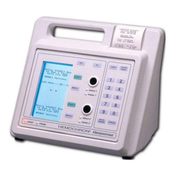
PRINCIPLES OF OPERATION The patented HEMOCHRON clot detection module contains two test wells into which disposable unitized coagulation test tubes can be inserted. The test tubes (provided in a separately purchased test kit) contain reagents for a particular test and a precision magnet. - Page 3 Wells Keypad Figure 1. HEMOCHRON Response Whole Blood Coagulation System Two RS232 serial ports and a Centronix parallel port are included so that results and other information from the data storage module can be downloaded to the laboratory computer or printed elsewhere. The RS232 serial ports can also be used to connect an external barcode reader for importing Patient ID (PID) and/or Operator ID (OID).
-
Page 4: Attention Label
Patient/QC test reports can be created using a personal computer and ITC data management software programs ATTENTION LABEL An attention label on the rear of the HEMOCHRON Response instrument alerts users to accompanying documentation: Before using the HEMOCHRON Response instrument, it is essential that the contents of this Operator’s Manual are read and understood by the operator. -
Page 5: Specifications
144 BTU/hr) Environmental Ambient Temperature 15 to 30 °C Note: For more technical information, refer to the HEMOCHRON Response Whole Blood Coagulation System Service Manual. GETTING STARTED Unpacking and Inspection Before unpacking the system, determine the area where the system will be located. You will need a level and flat area that is approximately 30 cm (12 in) wide, 30 cm (12 in) deep, and 30 cm (12 in) high. - Page 6 Materials Provided Article Quantity HEMOCHRON Response Whole Blood Coagulation Instrument AC/DC Power Module ITC Part Number HR1283 Power cord (see note below) Seiko Thermal Paper 1 roll Operator’s Manual HRDM V3.0 software program RS232 Computer Interface Cable Materials Required But Not Provided...
- Page 7 Set the COM port location as described on page 19. Connecting a Bar Code Reader A bar code reader can be attached to the HEMOCHRON Response for use in entering parameters such as OID and PID. Note: Refer to page 39 for information on connecting the bar code reader and configuring the cable.
- Page 8 Enter PID, OID, PIN (optional), ESV serial number, and QC ranges. Select a menu option. YES (ENTER) Save the response to a prompt or the entered ID or PIN. Reject the response to a prompt. Left/Right Cursor Positioning. Page Up/Page Down.
- Page 9 Display Panel Operations such as running a test and prewarming a well can be carried out simultaneously on both wells. However, commands, prompts, and test results that appear on the display panel apply to a single well. The well for which commands are displayed is designated by the position of the divider bar (the bar in which the time and remaining battery power are displayed) (Figure 3).
- Page 10 The arrows designate the operation that will be halted if the CANCEL key is pressed. If an operation is canceled, the arrows will point to the next operation that can be canceled. If an operation cannot be canceled, arrows are not displayed. Note: Pressing CANCEL shuts down a test, removes any related menus, sets the assay to the default assay, sets the record type to Patient, resets the OID or PIN and resets all lockouts.
-
Page 11: Setting Supervisor Options
Note: Refer to the package insert accompanying the HEMOCHRON test tubes for storage and handling instructions. ITC test tubes for the HEMOCHRON Response Whole Blood Coagulation System contain a barcode label imprinted with the test name and expiration. When these tubes are placed in the test well, the instrument automatically reads this information and selection of the test from the test menu is unnecessary. - Page 12 To Display the Supervisor Menu: Display the second page of the main menu. Press 4 to display the Enter Passcode prompt. Enter the passcode. Press YES to accept. The first page of the Supervisor menu is displayed. Press MENU once or twice to display the second or third page of the Supervisor menu. Note: The next or previous pages can also be displayed by pressing 0 or 9.
- Page 13 Displaying the Clock The time can be displayed on the separator bar of the display panel. Display the first page of the Supervisor menu. Press 5 to display the Clock line. ON will be displayed after the Clock line. Note: Displaying the clock operates as a toggle. If clock is already specified (displayed as ON), it can be canceled by pressing 5 again to display OFF.
- Page 14 Specifying the Length of Time a PID will be Reused After a PID is entered, it can be displayed as a default entry for a specified number of hours. Display the first page of the Supervisor menu. Press 2 to display the PID Setup menu. Press 3 to display the Enter Reuse Hrs prompt.
- Page 15 Specifying OID, PIN, and Test Permissions for an Operator Note: HRDM V. 3.0 or higher software can be used to manage operator tables. Display the first page of the Supervisor menu. Press 3 to display the OID Setup menu. Press 2. The Edit User Codes list is displayed: Note: Up to 504 users can be specified.
- Page 16 Specifying QC Lockouts Display the second page of the Supervisor menu. Press 6 to display the first page of the QC Lockout menu: To specify whether LQC must be run at specified intervals, press 1 until the desired selection is displayed: •...
- Page 17 Display the second page of the Supervisor menu. Press 7. In response to the prompt, enter the number of the note (1 to 9) to be created or changed. The User Note screen is displayed, with the cursor positioned on the first character of the note...
-
Page 18: Setting Output Options
Connect the COM 1 or the COM 2 port of the HEMOCHRON Response to the personal computer. Using the corresponding MENU key (MENU 1 for the COM 1 port, MENU 2 for the COM 2 port) display the second page of the Supervisor menu. - Page 19 Enabling Display of Remaining Battery Power The amount of power remaining in the battery can be displayed either as a numerical percentage or as a bar indicator. Press 1 in Set Outputs. YES is displayed after the Battery % line: 1 –...
-
Page 20: Setting Program Options
Enabling Logging of Data The data-logging feature is used to send raw data, obtained during an assay, to an external computer or printer. This feature is most useful for troubleshooting. Note: An external printer or computer must be connected and enabled before the data-logging feature can be operated. -
Page 21: Customizing The Printed Heading
CUSTOMIZING THE PRINTED HEADING The heading at the top of each printout can be customized. Press MENU twice and press 3 to display the Print Heading screen. The cursor is positioned on the first character of the heading and the selection block is positioned at the space: Cursor Selection Block Press 8 to move the selection block right one character, press 7 to move the selection block left... - Page 22 Prewarming a Well Certain tests require prewarming prior to blood sample introduction. Note: Consult individual test package inserts for the required prewarming time. Press MENU to display the first page of the main menu. Press 3 to display the Prewarm Well menu. Press the numeral key corresponding to the length of prewarming time.
- Page 23 To Display the RxDx menu: Note: The RxDx module is an additional feature of the Response system. Information can be requested from your local HEMOCHRON representative or ITC Customer Service on how the RxDx module can be activated.
- Page 24 Starting the Test Consult the individual test package insert to determine the volume of sample and appropriate test procedure to use. Dispense the sample into the test tube and simultaneously press the START key. A beep will signal the start of the test and timing of the test begins. Mix the contents of the test tube.
- Page 25 Aborting a Test A test can be aborted once the timing has begun. Press CANCEL. The instrument will display Hit YES to Abort. Press YES to stop the test. Note: The test can also be aborted by removing the tube after the test has been running for 15 seconds.
- Page 26 Storage of Results Patient and quality control test results are automatically stored when the test is completed. The OID, PID or QC tag, and date and time each test was run are stored with the results for each test. Instrument Shutdown To shut down the system, press either START key and hold it down.
-
Page 27: Quality Control (Qc)
Testing test tube reagents in accordance with the Package Insert for each assay, using two levels of liquid controls. Self-Check The HEMOCHRON Response instrument performs a “self-check” every time it is activated and a test is performed. When a test is initiated by pressing START, system checks are automatically performed and include: •... - Page 28 QC Using Liquid Controls The instrument can also be tested at any time using LQC products. Note: HEMOCHRON LQC products are available from ITC. Refer to the LQC package insert for procedural description. To Run LQC: Press MENU to display the first page of the main menu.
-
Page 29: Operating Precautions
HEMOCHRON Response test results should always be scrutinized in light of a specific patient’s condition or anticoagulant therapy. Any test results exhibiting inconsistency with the patient’s clinical status should be repeated or supplemented with additional diagnostic tests. -
Page 30: Results Management
Caution: Verify that any third-party connectivity software to be used is compatible with the software version of the HEMOCHRON Response instrument in use. Transferred data will be lost if third-party connectivity software is used with non-compatible versions of HEMOCHRON Response software. - Page 31 Press 1 to display search options. Press the number corresponding to a search category. Enter the appropriate response to any prompts and press YES. The most recent matching record is displayed. Press 0 or 9 to display other records in ascending or descending order.
-
Page 32: Default Settings
DEFAULT SETTINGS Factory default settings for the HEMOCHRON Response system are listed below: Parameter Value Well1 Records PAT = 0; QC = 0 Well2 Records PAT = 0; QC = 0 Battery % Plot Test COM1 Port COM2 Port INT Print... -
Page 33: Troubleshooting
TROUBLESHOOTING Hazard and Fault Messages The hazard and fault messages that may be displayed while operating the system are listed in the following table. The hazard/message, the probable cause, and corrective action are shown for each message. ITC Technical Service can be contacted by phone at (800) 631-5945 or (732) 548-5700, by FAX at (732) 548-9824, or by e-mail at techservice@itcmed.com. - Page 34 Hazard/Message Cause Corrective Action ACCESS User OID/PIN did not match the Contact facility POCC or supervisor for proper DENIED/UN- supervisor authorization table, or authorization. AUTHORIZED the user is not authorized for the OPERATOR test type indicated. If START button is pressed and a test tube is Auto SHUT-OFF Automatic shut off of a test.
-
Page 35: System Tests
Printer and COM Warnings Warning messages may also be displayed during operation of the printer or during transfer of data. The warning message indicates that the operation could not be completed and that corrective action must be taken. Instrument operation will continue if a Printer or COM warning is displayed. The warning messages that may be displayed are described below. - Page 36 To Run a System Test: Display the second page of the main menu. Press 5 to display the first page of the System Test menu. Press MENU or 0 to display the second page. Select a test by pressing the corresponding numeral key. Follow the instructions for each test as outlined in the following sections.
- Page 37 To Test the Internal Printer: Select the first System Test menu. Press 7. The Internal Printer menu is displayed. Select the desired option using the numeric key to start the test. Examine the printouts to determine that the corresponding characters are legibly printed. To Test the Battery: Select the second System Test menu.
-
Page 38: Maintenance
Note: Follow this procedure before shipping the instrument to a service center. Fan Filter Replacement For those HEMOCHRON Response instruments equipped with a user serviceable filter, the filter is mounted on the underside of the instrument and held within a plastic housing by means of a snap-in retainer plate (see Figure 10). -
Page 39: Specifications For Peripherals
SPECIFICATIONS FOR PERIPHERALS Specifications for Bar Code Reader Any bar code reader which meets standard IEC 60825 and has the specifications and ASCII output below may be used. Note: Call ITC Technical Service at (732) 548-5700 for product recommendations. Configure the bar code reader from the default condition as follows: Selection Scan Variables... - Page 40 Preparing a Serial Cable for Connecting a Printer or Computer Cable configurations for connecting a serial printer or a computer depend upon the type of connector on the device (Figure 12). Use 6-wire or 8-wire RJ45 to RJ45 modular straight through connecting cable no longer than 25 feet plus an RJ45 to DB9 adapter.
-
Page 41: Safety Standards
SAFETY STANDARDS The HEMOCHRON Response instrument complies with the following safety standard requirements and directives: CSA C22.2. 601.1. Medical Electrical Equipment – General Requirements for Safety EN 60601-1 / Medical Electrical Equipment – General Requirements for Safety IEC 60601-1/ UL 60601-1 EN 60601-1-2 / Medical Electrical Equipment –... -
Page 42: Index
............18 fault list ............37 beep volume............20 flashlight time ..........20 changing printed heading .......21 hazard and fault messages......33 checking system operation......35 HEMOCHRON Response clock..............13 description ...........3 displaying ...........13 features ............4 format ............12 specifications ..........5 coagulation testing description ...........2 tests run ............2... - Page 43 aborting a test ..........25 serial cable ............39 display of results ........25 setting entering OID ..........22 date ............12 entering PID..........22 date format..........12 entering PIN ..........22 time............12 prewarming..........22 time format..........12 specifying the test........22 shutdown............26 starting the instrument......21 specifications.............5 starting the test ..........24 bar code reader..........39 operational principles ........2 dimensions ..........5...
- Page 44 HR1574 10/04 Printed From ITC Intranet...
Need help?
Do you have a question about the Response and is the answer not in the manual?
Questions and answers