Table of Contents
Advertisement
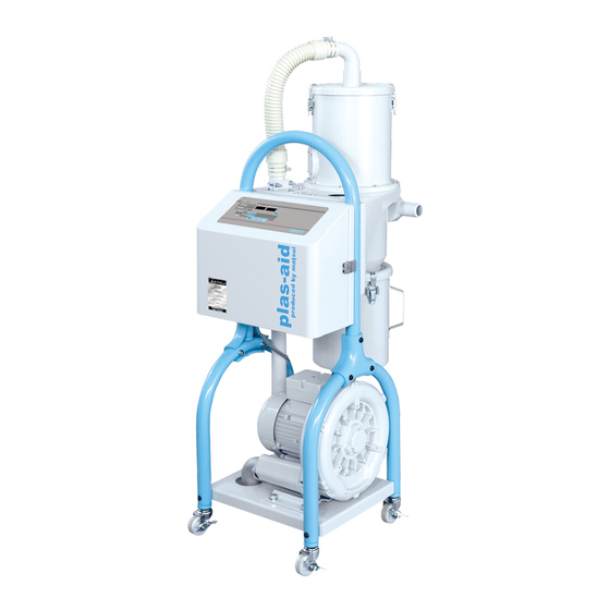
JET LOADER
JL4-V・VC-3~6 MODELS
(U version)
OPERATION MANUAL
WARNING
Thank you for choosing our product.
Before operating this equipment, please read this manual thoroughly.
Keep this manual in a location near the equipment so that it may be readily
referred to whenever a question arises during equipment operation.
Issued March 2005
Advertisement
Table of Contents

Subscribe to Our Youtube Channel
Related Manuals for Matsui JL4-5V-3~6

Summary of Contents for Matsui JL4-5V-3~6
- Page 1 JET LOADER JL4-V・VC-3~6 MODELS (U version) OPERATION MANUAL WARNING Thank you for choosing our product. Before operating this equipment, please read this manual thoroughly. Keep this manual in a location near the equipment so that it may be readily referred to whenever a question arises during equipment operation. Issued March 2005...
- Page 2 Introduction Thank you for purchasing of our JL4 JET LOADER. Please read this manual carefully for proper and safe operation. This instruction manual contains warranty information. Please carefully store this manual after you have read it. 1. Warranty Period If any defect is found in our equipment under normal operating conditions, and we determine it to be a defective, we will repair it or replace the parts free of charge within the following period and terms: 1)...
-
Page 3: Table Of Contents
Contents The following marked chapters are very important. Please read them in advance and pay attention to them. Introduction Conte ································································································································· I - II Chapter 1 Configuration of Equipment 1. Product model ·················································································· 1 2. Flow diagrams ·················································································· 2 3. Packing list ······················································································· 4 Chapter 2 For Safe Operation 1. -
Page 4: Contents
Contents Chapter 6 Operational Descriptions and Timing Charts 1. Jet Clone types- limit or level switch control collection hopper ······· 25 2. Vacuum hopper types, E2K control collection hopper ····················· 27 3. Jet Clone types- cylinder control or suction hopper type ASD control collection hopper ·············································································... -
Page 5: Chapter 1 Configuration Of Equipment
Chapter 1 Configuration of Equipment The following marked chapters are very important. Please read them in advance and pay attention to them. 1. Product model Collection Hopper and Control Procedure Collection Hopper Control Procedure Limit control Jet Clone Level switch control Cylinder control E2K control Vacuum hopper... -
Page 6: Flow Diagrams
Chapter 1 Configuration of Equipment 2-way valves are shown in the following diagrams, however, in actuality, 3-6-directional valves can additionally be installed. Flow diagrams (V type) Flow diagram type 1 Flow diagram type 4 Suction hose Jet Clone type GL-1V Hose cylinder control Jet Clone type limit control... - Page 7 Chapter 1 Configuration of Equipment 2-way valves are shown in the following diagrams, however, in actuality, Flow diagrams (VC type) the valve is additionally installed in 3 to 6 directions, similarly. Flow diagram type 6 Flow diagram type 9 GL-1V Hose Jet Clone type Jet Clone type cylinder control...
-
Page 8: Packing List
Chapter 1 Configuration of Equipment Packing list Please confirm that all purchased devices are included. Component Name Style of Packing ●Vacuum unit 3~6 way selector valve JL4-(4,5,6)V-3~6 type ●Vacuum unit JL4-(4,5,6)VC-3~6 type 3~6 way selector valve ●Nylon hose Aperture φ6, Length 5m (Standard)... - Page 9 Chapter 1 Configuration of Equipment Component Style of Packing Name ● Jet Clone type limit control Collection hopper ● Jet Clone type level switch control ● Suction hopper type E2K control * This unit is supplied with an injection molding machine match base or chute. ●...
- Page 10 Chapter 1 Configuration of Equipment Style of Packing JL4-4V(VC) JL4-5V(VC) ● Conveying hose (φ38 PVC hose) JL4-4V(VC): Length 15 ft. JL4-5V(VC): Length 15 ft. ● Vacuum hose (φ38 GTG hose) Length 15 ft. ● Hose band (One set is 4 pcs.) Material &...
-
Page 11: Chapter 2 For Safe Operation
Chapter 2 For Safe Operation This chapter contains instructions for operation, maintenance, and repair to operate this equipment properly and safely. Also, this chapter explains the labels and meaning of each indication on the product. WARNING Indications for safety described in this manual should be observed when operating or inspecting this product. -
Page 12: Items To Be Observed For Safety
Inspection and replacement by persons without sufficient knowledge about the product may cause defects or danger. When maintenance or repair advice is necessary, contact the Matsui service department, or your local sales representative. - 8 -... -
Page 13: Labels
Chapter 2 For Safe Operation CAUTION 1) Disposal of the product and parts This product and parts are handled as industrial waste and are regulated by the “Waste Disposal and Public Cleaning Law.” Request subcontractors who have received an “industrial waste collecting and transporting permit”... -
Page 14: Mounting The Collection Hopper
Chapter 3 Installation This Chapter describes installation work of the product for each piece of equipment according to the procedure. Mounting collection hopper 1) Jet Clone type limit, level, cylinder control Material port hose Vacuum port hose Material port hose Pneumatic Jet Clone Jet Clone... - Page 15 Chapter 3 Installation NOTE ○ The hopper on which the Jet Clone is mounted should be sized so that the damper of the Jet Clone does not contact the inner wall of the hopper. ○ Install the Jet Clone horizontally. Otherwise, it may not accurately detect the hopper is full of material.
- Page 16 Chapter 3 Installation 2) Vacuum hopper type- E2K control Inlet Vac. hose Vacuum hopper Material port hose Proximity switch (E2K) Molding machine Step Task Description Mounting the base Attach the base to the molding machine. 1 (Fix with hexagon socket head cap screws.) *...
- Page 17 Chapter 3 Installation 3) Vacuum hopper type ASD control (not common) Material port hose Vacuum hopper Vacuum port hose Hopper Level switch Task Description Step Drilling the mounting Drill holes in the hopper to be mounted so that they match the holes mounting holes in the Jet Clone.
-
Page 18: Installation
Chapter 3 Installation 2. Installation Install the equipment as shown in 2. Flow diagrams in Chapter 1. Step Task Description 1 Installing the Loader Install the loader near each collection hopper (within the reach of the 5m-long air suction hose) in the vicinity of respective collectors. *... - Page 19 Chapter 3 Installation Task Description Step Connect an air hose of compressed air source from your facility 5 Supplying compressed to the air supply valve (1/4”) of the 3~6 way valve. air to the (3 ~ 6 way) selector valve Fully open the valve of the air kit to supply dry compressed air of 0.5 MPa or higher from the compressed air source.
- Page 20 Chapter 3 Installation Step Description Task Supplying compressed 6 Connect an air hose for a compressed air source to the air supply air to collection hopper port valve of the automatic slide gate air kit from your existing source. air kit *...
-
Page 21: Connecting The Power
Chapter 3 Installation 3. Power cord Information WARNING! Only qualified personnel should attempt any electrical connections! Task Description Step Turn OFF the primary power of your existing source. 1 Connecting / Checking ↓ the power cord After checking that the power breaker in the control panel is OFF, check the 15ft. - Page 22 Chapter 3 Installation Task Description Step ↓ 3 Checking forward and If no air is blowing out from the exhaust port, it means that the blower reverse phase rotates in the reverse direction (reverse phase). In this case, turn OFF the primary power and reverse the R phase and T phase of the three wires of the power cord.
-
Page 23: Chapter 4 Preparations For Operation
Chapter 4 Preparations for Operation This chapter describes checks before starting operation. Check status of each component Unit to be checked Check Filter case for suction unit Check that the cartridge and cap are set to the filter case. Filter case Filter case Separator Dust box... - Page 24 Chapter 4 Preparations for Operation Unit to be checked Check Check that no foreign matter intrudes inside, and further check that the Each collection hopper packing and metal mesh filter are properly set. After checking, firmly fix the lid of the collection hopper with the catch clips (3 pieces).
-
Page 25: Control Panel Description
Chapter 4 Preparations for Operation Control panel description ・ Discharging display/Engineering setting mode display (green) ・ Conveying display/User setting mode display (green) ・ Digital displayer (red) PV value/Function ・ Digital displayer (green) ・ Reset switch SV value/Parameter Jet Loader / F u n c t i o n /P a r a m e t e r Conveyance /User Setting... -
Page 26: Chapter 5 Operating Procedures
Chapter 5 Operating Procedures This Chapter describes starting, stopping and cleaning procedures according to the steps. Starting procedure Step Description Display Operation Turning on power Turn ON the power breaker in the control panel. 1 2 The display Starting operation Press a desired switch from the No. 1 start/stop corresponding to switch to the No. -
Page 27: Stopping Procedure
Chapter 5 Operating Procedures Stopping procedure Step Operation Description Display 1 Stopping Press a desired switch from the No. 1 start/stop The display operation corresponding to switch to the No. 6 start/stop switches operation of on the operation panel. through ↓... -
Page 28: Cleaning Procedure
Chapter 5 Operating Procedures 3. Cleaning procedure This section describes the procedure for cleaning the conveying hoses and collection hoppers after stopping equipment operation. Step Operation Description Display Preparation work Remove the suction nozzle at the end of the conveying hose from the material supply section. -
Page 29: Jet Clone Types- Limit Or Level Switch Control Collection Hopper
Chapter 6 Operational Descriptions and Timing Charts This Chapter describes the operation for the collection hopper. 1. Jet Clone type limit or level switch control collection hopper Description of operations Set the control panel power circuit breaker to ON. ↓ Gate operations ダンパー動作説明図... - Page 30 Chapter 6 Operational Descriptions and Time Charts Timing chart The following is the time chart for No.1 and No. 2 directions, however, operation for No. 3 direction or more is similarly carried out. Start/stop switch Full Request Request No. 1 Request signal Full Request No.
-
Page 31: Vacuum Hopper Types, E2K Control Collection Hopper
Chapter 6 Operational Descriptions and Time Charts Suction hopper type E2K control collection hopper Description of operations Set the control panel power circuit breaker to ON. ↓ When the equipment starts conveyance by the start of operation, the blower starts rotating in response to the request signal from the E2K. - Page 32 Chapter 6 Operational Descriptions and Time Charts Timing chart The following is the time chart for No.1 and No.2 directions, however, operation for No.3 direction or more is similarly carried out. Start/stop switch Full Request Request No.1 Request signal Full Request No.2 Request signal Operating...
-
Page 33: Collection Hopper
Chapter 6 Operational Descriptions and Timing Charts 3. Jet Clone cylinder control or suction hopper type SD control collection hopper Description of operation Set the control panel power circuit breaker to ON. ↓ When the equipment starts conveyance by the start of operation, the discharge timer starts and after the lapse of the preset time, the blower starts rotating in response to the request signal from the level switch. - Page 34 Chapter 6 Operational Descriptions and Timing Charts Timing chart The following is the time chart for No.1 and No.2 directions, however, operation for No.3 direction or more is similarly carried out. Start/stop switch Full Request Request No.1 Request signal Full Request No.2 Request signal Operating...
-
Page 35: Respective Parameter Setup
Chapter 7 Respective Parameter Setup This chapter describes respective parameter setup carried out on the operation panel. Respective parameter setup is classified into user setting mode and engineering setting mode. NOTE The parameters of the engineering setting mode have been set according to the specification at shipment or at installation. - Page 36 Chapter 7 Respective Parameter Setup Setting Initial Code Setting item Function range value No. 1 The timer should be set for No.1 conveyance 0 - 999 sec Conveyance time. timer The time for conveyance varies with the conveying distance, the type of material, and the type of collection hopper.
- Page 37 Chapter 7 Respective Parameter Setup Engineering setting mode Setting Initial Code Setting item Function range value No. 1 5 sec The timer should be set for the time to judge 0 - 99 sec Request signal No.1 request signal. delay timer The timer should be set so as to disregard a false request signal in short time due to flowing of material.
- Page 38 Chapter 7 Respective Parameter Setup Setting Initial Code Setting item Function range value No. 2 This should be set for the type of No. 2 Same as Same Request signal request signal. above input select Hereinafter same as above. above No.3 Request This should be set for the type of No.
- Page 39 Chapter 7 Respective Parameter Setup Setting Initial Code Setting item Function range value Batch gate This should be set for interlocking conveying oFF, interlocking direction when the batch conveyance option is 1,2,3,4,5,6 direction performed. oFF: No batch conveyance Interlocking in No. 1 direction Interlocking in No.
-
Page 40: Setting Procedures
Chapter 7 Respective Parameter Setup 2. Setting procedure The codes for each setting item are displayed on the left digital display (red). The set values are displayed on the right digital display (green). NOTE Carry out the respective setting procedures after stopping operation. The setting mode cannot be turned on during operation . - Page 41 Chapter 7 Respective Parameter Setup Engineering setting mode Keep pressing the SV switch for five seconds or longer. The Engineering Setting Mode display blinks. Codes for setting items and set values are displayed on the digital display. Operate in the same way as the User Setting Mode from now on. After the setting procedure is completed, the mode returns to the normal mode when the SV switch is kept depressed for five seconds or longer.
-
Page 42: Inspection And Maintenance
Chapter 8 Inspection and Maintenance This chapter describes inspection and maintenance items and the procedures in order of inspecting frequency in order to always keep the product in a favorable state. Daily inspection Maintenance and Descriptions inspection item 1. After removing a catch clip on the filter case, remove the filter Cartridge filter within filter case lid.[①→②] case of the suction unit... - Page 43 Chapter 8 Inspection and Maintenance Maintenance and Descriptions inspection item Discharging dust in suction V type unit Remove the cap below the filter case and discharge the accumulated dust. Be sure to recover after discharging. VC type Remove the catch clip on the upper part of the dust box and discharge the accumulated dust.
- Page 44 Chapter 8 Inspection and Maintenance Maintenance and Descriptions inspection item Pull up the adjusting knob of the filter regulator to unlock, turn the adjusting Air kit for slide gate of knob the to left, and check that the indicated pressure on the pressure collection hopper gauge has reached “0 (zero)”...
-
Page 45: Monthly Inspection
Chapter 8 Inspection and Maintenance Monthly Inspection Maintenance and Descriptions inspection item Open the lid of the collection hopper to take out the filter, and check that it Metal screen filter inside the is not clogged. collection hopper If clogged, blow clean dry air to remove the deposits. Packing Filter Catch clip... - Page 46 Chapter 8 Inspection and Maintenance Maintenance and Descriptions inspection item A: Please check that the stopper (M6) on the upper and lower two Check each component of jet points are not loosened, respectively. clone ※Please retighten the stopper according to the “Stopper adjusting diagram”...
- Page 47 Chapter 8 Inspection and Maintenance Maintenance and Descriptions inspection item Check each component of jet clone Upper stopper adjustment position Limit switch ON position Lower stopper adjustment position (Clearance 6mm) Stopper adjustment diagram - 43 - [WO-4841;JL4-V・VC-3~6-43]...
-
Page 48: Component Adjustment Procedure
Chapter 8 Inspection and Maintenance 3. Component adjustment procedure This section describes the adjustment procedure of the full detecting device attached to each collection hopper. Jet Clone gate cam Adjust the gate cam when full is not detected Limit switch regardless of whether the material is full. - Page 49 Chapter 8 Inspection and Maintenance Suction hopper level switch If the level switch does not accurately detect the full level for the material used, make a sensitivity adjustment of the level switch. Adjust the sensitivity according to the specific gravity of the material. Step Details of operation Set the control panel power circuit breaker to ON.
- Page 50 Chapter 8 Inspection and Maintenance Suction hopper proximity switch (E2K) If the proximity switch does not detect the full level, make a sensitivity adjustment of the proximity switch by the following steps. Step Details of operation Remove the materials in the collection hopper. Turn ON the power circuit breaker on the control panel.
-
Page 51: Operation Check Procedure Of 3-6 Way Selector Valve
Chapter 8 Inspection and Maintenance 4. Operation check procedure of 3 – 6 way selector valve Manually operate the 3 – 6 way selector valve and describe the Operation check the Operation check procedure according to the steps. Step Details of operation Turn OFF the power breaker on the rear face of the control panel. -
Page 52: Operation Check Procedure Of Automatic Slide Gate
Chapter 8 Inspection and Maintenance 5. Operation check procedure of automatic slide gate In the case of the suction hopper type SD control collection hopper, manually operate the automatic slide gate. The methods for checking the operation are described according to the steps. - Page 53 ・ If the “E0” is displayed even after turn it “ON” again. restarting, the control board has failed. ・ Contact your local Matsui SDI dealer. ・ Remove the material in the ・ When the suction part (metal “E 3”...
- Page 54 (see replace the filter. ・ Contact your local Matsui SDI dust box. Chapter 8 Inspection and Maintenance). dealer for a new filter. ・ Set the dust cleaning count (dUP) to “0”...
- Page 55 Chapter 9 Troubleshooting Location to be Code Action Precaution checked ・ Remove the material ・ When the suction part (metal “E 23” Check that material is No. 3 Conveying not clogged in the in the conveying hose. mesh) on the secondary air ・...
- Page 56 Chapter 9 Troubleshooting Location to be Code Action Precaution checked ・ Remove the material ・ When the suction part (metal “E 25” Check that material is No. 5 Conveying not clogged in the in the conveying hose. mesh) on the secondary air ・...
- Page 57 Even if it is normal, replace by the time the above times are reached or within 2 years after starting use. Entrust Matsui SDI or your employee who has sufficient working knowledge of electricity to carry out inspection or exchange, since the operation includes the potential for failure or danger.
- Page 58 If switching does not function properly, breaker on the control panel is replace the power breaker. “ON.” Entrust Matsui SDI or your employee who has sufficient working knowledge of electricity to carry out inspection or exchange, since the operation includes the potential for failure or danger.
- Page 59 Check that the suction hopper Refer to Chapter 8 Inspection For purchase of the proximity switch and proximity switch detects and Maintenance to adjust the type, contact Matsui SDI. normally. sensitivity of the proximity switch. * Only when the suction...
- Page 60 Matsui SDI. electromagnetic valve. * Only when the suction If the damper still does not Entrust Matsui SDI or your employee who hopper type SD control close, replace the has sufficient working knowledge of collection hopper is used.
- Page 61 In addition, if the packing is significantly deteriorated, deformed, discolored or hardens, replace it with a new one. For purchase of the packing and cartridge filter and type, contact Matsui SDI. Check that the 2-way selector Refer to Chapter 8 Inspection For purchase of the electromagnetic valve is properly selected.
- Page 62 Material 材 料 Check that the Jet Clone gate is Check the end of the damper Contact Matsui SDI for replacement of completely opened. solenoid and repair any the end. abnormality. * Only when the Jet Clone type limit type collection hopper is used.
- Page 63 12735 Suction hose Tigers Polymer /one Every year (GL-IV hose) 12736 direction Packing Matsui Mfg Co. NBR U-packing Every year (for filter case lid) Packing Matsui Mfg Co. NBR U-packing Every year (for dust hopper lid) Cartridge filter Matsui Mfg Co.
- Page 64 1) Resin used: ABS virgin pellets with an apparent specific gravity of 0.63. 2) Suction distance: 5m. The conveying distance (5 to 30m) includes a vertical distance of 3m. 3) Hose used: PVC hose, Nozzle used: made by Matsui 4) Standard combined Jet Clone 2.
- Page 65 Chapter 12 Option The following options are available for this equipment. Please make sure that correct options are installed * The unit shown above is a suction unit of the type JL4-VC CR-1 Tr-0 ELB-1 Inside of control panel - 61 - [WO-4841;JL4-V・VC-3~6-61]...
- Page 66 Chapter 12 Option ①: Leakage circuit breaker The leakage circuit breaker, if attached to the power circuit breaker, will protect the equipment against a ground fault, an overload or short-circuit, thus preventing electric shock hazards. (E) (R) (S) (T) AC 3-phase power supply 50/60Hz 三相交流電源 50/60Hz ELB-1 Symbol...
- Page 67 Chapter 12 Option 2B: Alarm buzzer At the time of dusting operation, the buzzer sounds, alerting operators in a wide working area. The buzzer sound can be stopped by a pushbutton. PB-R1 Buzzer reset ブザー リセッ ト CR-1 Alarm 警 報 Symbol Name Maker...
- Page 68 If the automatic slide gate is installed below the receiver tank, material can be stopped during conveyance. The blower stops after blowing air into the conveying pipe. Symbol Name Model Maker ASD φ70 automatic gate Automatic slide gate MATSUI Chute MATSUI SUS-304 Suction box MATSUI SUS-304 ④: Operating voltage 100V AC The supplied voltage 200V AC is transformed down to an operating voltage of 100V AC by the internal transformer.
- Page 70 ITEM NO. DESCRIPTION REQ.D MATERIAL REFERENCE Model Voltage Fuses Motor Protectors TR-1 Contoroler(1,2WAY Type) G2842-JLD2 Matsui AC230V 140-C2E-B63(4.8A) FNQ-R-2 JL4-4 Contoroler(3-6WAY Type) G2842-JLD6 Matsui FNQ-R-1 AC460V 140-C2E-B25(2.5A) SW-1 Operation ON-OFF EATON 8006K23NIV2 140-C2E-B63(5.8A) FNQ-R-2 AC230V PB-1 Alarm Silence P9XPNN & P9B10VN...
- Page 71 Standard dwg. 標準図 SCALE CODE NO. APPROVED BY NISHI FORM CIRCUIT DIAGRAM 1 DWG. T05014 NAME DSGND(CHKD)BY - - DATE SEP/23/2005 元図 DWG. NO. A301108 PLANE DRAWN BY M.TAKANO UNIT mm MARK DATE CONTENTS CHKD APPD TRIGONOMETRY...
- Page 72 Standard dwg. 標準図 SCALE CODE NO. 700203 APPROVED BY NISHI FORM CIRCUIT DIAGRAM 2 DWG. T05015 NAME DSGND(CHKD)BY - - DATE SEP/23/2005 元図 DWG. NO. A301110 PLANE DRAWN BY M.TAKANO UNIT mm MARK DATE CONTENTS CHKD APPD TRIGONOMETRY...
- Page 73 Standard dwg. 標準図 SCALE CODE NO. 700203 APPROVED BY NISHI FORM CIRCUIT DIAGRAM 3 DWG. T05016 NAME DSGND(CHKD)BY - - DATE OCT/19/2005 元図 DWG. NO. A301140 PLANE DRAWN BY M.TAKANO UNIT mm MARK DATE CONTENTS CHKD APPD TRIGONOMETRY...
- Page 74 IN CASE OF LIMIT SWITCH CONTROL IN CASE OF CAPACITIVE PROXIMITY SENSOR(DC) CONTROL リミットスイッチ制御の場合 静電容量形近接センサー(DC)制御の場合 No.1 LEVEL SIGNAL No.1 PROXIMITY SWITCH LS-1 E2K-1 No.1 レベル信号 No.1 近接スイッチ No.2 LEVEL SIGNAL No.2 PROXIMITY SWITCH LS-2 E2K-2 No.2 レベル信号 No.2 近接スイッチ No.3 LEVEL SIGNAL No.3 PROXIMITY SWITCH LS-3 E2K-3...
- Page 75 JET-CLONE/SLIDE DAMPER VACUUM HOPPER/CYLINDER VACUUM HOPPER JET-CLONE MAI STYLE (WITH PADDLE-TYPE LEVEL SWITCH) ジェットクロン ジェットクロン/排出弁付吸引ホッパー JET LOADER (パドル式レベルスイッチ制御) CN-S1~S6 ジェットローダー CN-S1~S6 PIN NO. FEED TO JC/SJC/CJC CN-S1~S6 JL4-4/5/6V(C) ピン番号 NO.1 NO.2 NO.3 NO.4 NO.5 NO.6 CN-S1~S6 PIN NO. FEED TO ピン番号...
Need help?
Do you have a question about the JL4-5V-3~6 and is the answer not in the manual?
Questions and answers