
Related Manuals for Psion Teklogix 7035

Summary of Contents for Psion Teklogix 7035
- Page 1 7035/8255/8260 Terminals User Manual September 8, 2003 Part No. 80439.I ISO 9001 Certified Quality Management System...
- Page 2 © Copyright 2003 by Psion Teklogix Inc., Mississauga, Ontario This document and the information it contains is the property of Psion Teklogix Inc., is issued in strict confidence, and is not to be reproduced or copied, in whole or in part, except for the sole purpose of promoting the sale of Psion Teklogix manufac- tured goods and services.
- Page 3 Disclaimer Every effort has been made to make this material complete, accurate and up-to-date. Psion Teklogix Inc. reserves the right to make changes without notice and shall not be held responsible for damages resulting from reliance on the material presented...
-
Page 5: Table Of Contents
2.1.1 Client-Side Emulation Software....15 Preparing The 7035 For Operation ....15 2.2.1 Connecting The 7035 Whip Antenna . - Page 6 2.10.3 Scanning Techniques..... 37 2.11 Infrared (IrDA) Port – 7035 Only ....37 2.12 Low Temperature, Freezer and Outdoor Terminals .
- Page 7 3.2.6 The Macro Keys ......55 44-Key 7035 Keyboards......57 3.3.1 Accessing Alpha Characters.
- Page 8 Exiting Tekterm And Accessing The Display Menu...111 Working With Menus ......113 Teklogix 7035, 8255 & 8260 Terminals User Manual...
- Page 9 7.5.11 Watchdog Timer ..... . . 128 7.5.12 Power – 7035 Only ..... 129 7.5.13 Serial Number .
- Page 10 8.1.1 Entering Data With A Bar Code Reader ...199 The 7035 Battery......200 8.2.1 Lithium-Ion Battery Safety Precautions .
- Page 11 Antenna Types......212 The 7035 Picker Cradle ......212 8.8.1 Mounting Hardware .
- Page 12 Memory Expansion Board ......234 IrDA Port (7035 Only) ......234 Wireless Communication Options .
- Page 13 Radio Menus ......F-8 Teklogix 7035, 8255 & 8260 Terminals User Manual...
-
Page 15: Program License Agreements
Datalight is a registered trademark of Datalight, Inc. FlashFX™ is a trademark of Datalight, Inc. Copyright 1993-1999 Datalight, Inc., All Rights Reserved. Teklogix 7035, 8255 & 8260 Terminals User Manual... - Page 16 USE OF SUCH MATERIALS IN CONNECTION WITH PRODUCT(S), INCLUDING WITHOUT LIMITATION) ANY WARRANTIES OR MERCHANTABILITY OR FITNESS FOR A PARTICULAR PURPOSE. iii. In no event will licensor or its suppliers be liable for consequential, incidental or special damages. Teklogix 7035, 8255 & 8260 Terminals User Manual...
- Page 17 Product as established by Fortress. The foregoing states the entire liability of Fortress and the sole and exclusive remedy of the Customer with respect to infringement of third party intellectual property. xiii Teklogix 7035, 8255 & 8260 Terminals User Manual...
- Page 18 Customer may make backup or archival copies of Software and use Software on a backup processor temporarily in the event of a processor malfunction. Any full or partial copy of Software must include all copyright and other proprietary notices Teklogix 7035, 8255 & 8260 Terminals User Manual...
- Page 19 Documentation in any medium without the appropriate United States and foreign government licenses. The transfer or export of the software outside the U.S. may require a license from the Bureau of Export Administration. For questions call BXA at 202-482-4811. Teklogix 7035, 8255 & 8260 Terminals User Manual...
- Page 21 Manufacturer: Rob Williams Vice President of Engineering Psion Teklogix Inc. Ontario January 14, 2003 Legal Representative Domique Binckly Vice President International Sales Psion Teklogix S.A. France January 14, 2003 xvii Teklogix 7035, 8255 & 8260 Terminals User Manual...
-
Page 22: Approvals And Safety Summary
Manufacturer: Rob Williams Vice President of Engineering Psion Teklogix Inc. Ontario January 14, 2003 Legal Representative Domique Binckly Vice President International Sales Psion Teklogix S.A. France January 14, 2003 xviii Teklogix 7035, 8255 & 8260 Terminals User Manual... - Page 23 Manufacturer: Rob Williams Vice President of Engineering Psion Teklogix Inc. Ontario January 17, 2003 Legal Representative Domique Binckly Vice President International Sales Psion Teklogix S.A. France January 17, 2003 Teklogix 7035, 8255 & 8260 Terminals User Manual...
- Page 24 Manufacturer: Rob Williams Vice President of Engineering Psion Teklogix Inc. Ontario January 15, 2003 Legal Representative Domique Binckly Vice President International Sales Psion Teklogix S.A. France January 15, 2003 Teklogix 7035, 8255 & 8260 Terminals User Manual...
- Page 25 Do not operate the equipment without the covers and enclosures properly installed. NTENNA To avoid discomfort due to the local heating effect of Radio Frequency energy, do not touch the antenna when a terminal is transmitting. Teklogix 7035, 8255 & 8260 Terminals User Manual...
- Page 26 fire may result. AUTION Danger of explosion if a 7035 battery is incorrectly handled, charged, disposed of or replaced. Replace only with the same or equivalent type recommended by the manufacturer. Dispose of used batteries according to the instructions described in “Maintaining The 7035 Battery”...
- Page 27 1.3.1 Features ....... . . 5 1.3.2 The 7035 Hand-Held Terminal ..... 7 1.3.3 7035 Integrated Scanner Patent Numbers .
-
Page 29: Chapter 1: Introduction
Chapter 1: Introduction About This Manual 1.1 About This Manual This manual describes how to operate the Teklogix 7035, 8255 and 8260 terminals. Chapter 1: Introduction provides a basic overview of the 7035 hand-held terminal along with the 8255 and 8260 vehicle-mount terminals. -
Page 30: Text Conventions
Appendix E: AirFortress™ Secure Client explains how to install and set up Secure Client software on your terminal. Appendix F: Parameter Trees provides parameter trees for the 7035, 8255 and 8260 terminals. 1.2 Text Conventions Note: Notes highlight additional helpful information. -
Page 31: About The Terminals
About The Terminals 1.3 About The Terminals The 7035 hand-held terminal and the 8255 and 8260 vehicle-mount RF terminals all run DOS and can operate in a Teklogix narrowband or Teklan 902 spread spectrum RF system using the RF connectivity options listed in the “Features” section below. - Page 32 “on”. softkey labels are displayed at the bottom of all terminal screens, indicating the function of function keys <F1> to <F4> on the 7035 – <F1> to <F6> on vehicle-mounts. •...
-
Page 33: The 7035 Hand-Held Terminal
Chapter 1: Introduction The 7035 Hand-Held Terminal 1.3.2 The 7035 Hand-Held Terminal Figure 1.1 The 7035 Hand-Held – 36-Key And 44-Key Keyboards Teklogix 7035, 8255 & 8260 Terminals User Manual... - Page 34 Chapter 1: Introduction The 7035 Hand-Held Terminal Figure 1.2 7035-I With Optional Pistol Grip Handle Teklogix 7035, 8255 & 8260 Terminals User Manual...
- Page 35 Figure 1.3 7035 Peripheral Port Integrated Scanner IrDA Port Figure 1.4 Infrared (IrDA) Port Warning: Using controls or adjustments or performing procedures other than those specified herein may result in hazardous radiation exposure. Teklogix 7035, 8255 & 8260 Terminals User Manual...
- Page 36 • Manufactured. This field contains the terminal's date of manufacture. Figure 1.5 Safety Labels Teklogix 7035, 8255 & 8260 Terminals User Manual...
-
Page 37: 7035 Integrated Scanner Patent Numbers
Chapter 1: Introduction 7035 Integrated Scanner Patent Numbers 1.3.3 7035 Integrated Scanner Patent Numbers The integrated scanner used in the 7035 may be covered by one or more of the following U.S. patents: 4,360,798; 4,369,361; 4,387,297; 4,460,120; 4,496,831; 4,593,186; 4,603.262; 4,607,156; 4,652,750;... -
Page 38: The 8260 Vehicle-Mount Terminal - Lcd Only
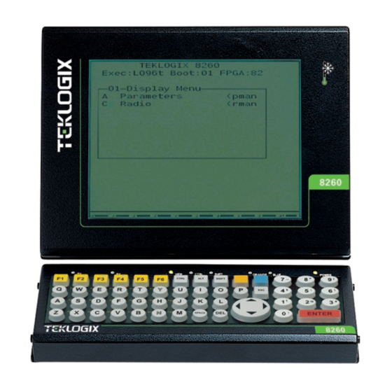
Chapter 1: Introduction The 8260 Vehicle-Mount Terminal - LCD Only 1.3.5 The 8260 Vehicle-Mount Terminal - LCD Only Figure 1.7 The 8260 Vehicle-Mount Keyboard Connector Scanner Expansion Port Port Figure 1.8 8260 Ports Teklogix 7035, 8255 & 8260 Terminals User Manual... - Page 39 2.5 Resetting Terminals.......25 2.5.1 Resetting The 7035......25 2.5.2 Resetting The 8255 And 8260 .
-
Page 40: Chapter 2: Assembly And Basic Operation
2.8.1 LEDs ........28 2.8.2 The Status Area – 7035 Only ..... . 28 2.8.3 Onscreen Indicators –... -
Page 41: Preparing Terminals For Operation
2.1.1 Client-Side Emulation Software For terminals equipped with the Client-Side Emulation feature, you’ll need to review the Connect Inc. manual, “Twin Client Reference for the 7035, 8255 and 8260 terminals manufactured by Psion Teklogix” that is shipped with your client-side emulation terminal. It details how to install and activate the client-side emulation software. - Page 42 • Press the button until the battery unlatches. Battery Release Button Figure 2.1 Battery Compartment Of The 7035 Terminal To install the battery pack: • Insert the battery pack with the textured plastic facing you. Click the battery into place.
-
Page 43: Attaching The 7035 Hand-Strap Or The Pistol Grip
Chapter 2: Assembly And Basic Operation Attaching The 7035 Hand-Strap Or The Pistol Grip 2.2.3 Attaching The 7035 Hand-Strap Or The Pistol Grip Note: For a list of additional accessories, refer to “Accessories List” on page 222. 2.2.3.1 Attaching The Hand Strap Note: A Phillips head screwdriver is required. -
Page 44: Installing 8255/8260 Vehicle-Mount Terminals
2. Using the cradle (PN 18457) and cradle mounting plate (PN 18197). Note: The bolts used for all installations are SAE 1/4-20. 18452 º Horizontal/vertical cradle º º Figure 2.2 The Horizontal/Vertical Mounting Cradle Teklogix 7035, 8255 & 8260 Terminals User Manual... -
Page 45: Using The Cradle And Cradle Mounting Plate
The choice of holes determines the angle at which the terminal tilts. Screw Holes Tabs Quick Release Fasteners Figure 2.3 The Terminal Cradle (PN 18457) Teklogix 7035, 8255 & 8260 Terminals User Manual... - Page 46 Slide the fasteners on the front of the cradle until they snap to the posts on the mounting plate. Warning: Never operate the vehicle if the quick release fasteners are not locked. Teklogix 7035, 8255 & 8260 Terminals User Manual...
-
Page 47: Mounting The 8260 Terminal
2.3.3 Mounting The 8260 Terminal 18452-001 Horizontal/vertical cradle º º 20164 (15 foot cable) 19448 (6 foot cable) 19449 (10 inch cable) º º 18239 Keyboard cradle 18451 Cradle support plate Figure 2.5 8260 Mounting Options Teklogix 7035, 8255 & 8260 Terminals User Manual... -
Page 48: Connecting The 8255/8260 Antenna
Protect cable runs from pinching, overheating and physical damage. • Protect cables by using grommets when cables pass through metal. • Prevent cables and connectors from moving and loosening by using plastic straps. Teklogix 7035, 8255 & 8260 Terminals User Manual... -
Page 49: Installing The Extension Power Cable
Connect the red wire from the diode assembly to a fused power source on the vehicle. It is recommended that all connections be secured with electrical tape or heat shrink to prevent contaminants from degrading the connection. Teklogix 7035, 8255 & 8260 Terminals User Manual... -
Page 50: Turning The Terminals On And Off
Press and hold down the <ENTER/ON> key for at least one second. Turning Off The 7035 Important: Turning the 7035 off does not result in a complete reboot; rather, the terminal enters a power-saving, “suspend” mode (assuming that a value other than ‘Disabled’ has been assigned to the power-saving parameter, “Power Down”... -
Page 51: 8255 And 8260 Vehicle-Mount Terminals
A reset will result in a complete reboot of the unit. When the terminal is reset, it reboots to the Tekterm application. 2.5.2 Resetting The 8255 And 8260 To reset the 8255 or 8260: • Using the On/Off switch, turn the terminal off and back on again. Teklogix 7035, 8255 & 8260 Terminals User Manual... -
Page 52: Working With The Startup "Display Menu
At this point, you’ll be asked to enter a password – either a supervisory or Teklogix level password. To exit the “Parameters” menu and return to the “Display menu” • Press <F2> – the PREVIOUS key – until the “Display Menu” is visible. Teklogix 7035, 8255 & 8260 Terminals User Manual... -
Page 53: The Keyboard
Type start at the DOS prompt, and press <ENTER>. 2.7 The Keyboard Teklogix offers a variety of keyboards for the 7035 hand-held and the 8255 and 8260 vehicle-mount terminals. All keyboards are equipped with a set of keys standard across all keyboards. These are described in “Keyboard Keys – A Description”... -
Page 54: Terminal Indicators
2.8.1 LEDs Transmit And Receive Two LEDs indicate the transmit and receive status of data. On the 7035, they are located on the left and right of the <SCAN> key. On the vehicle-mounts, the LEDs are located to the left on the keyboard and are labelled TX and RX •... -
Page 55: Onscreen Indicators - 7035 Only
LEDs to indicate various terminal states. Important: The “One-Shot Mode” parameters described on page 121 are used to alter the behaviour of the 7035 modifier keys – that is, how these keys are locked “on” and unlocked. Onscreen... - Page 56 802.IQ Blank – If a LINK onscreen message does not appear, the radio is not within communicating range of a configured and operating base station. Table 2.1 7035 Onscreen Indicators Teklogix 7035, 8255 & 8260 Terminals User Manual...
-
Page 57: Softkeys
A horizontal bar graph, referred to as a battery gauge, is displayed in the status area of the 7035 terminal screen. It keeps track of the percentage of remaining battery power capacity – 0 to 100%, resolution 10% of nominal. The number on the right-hand side of the bar graph indicates the maximum capacity of the battery (in milliampere hours). -
Page 58: Beeper Volume -
You can then press the <F3> or <F4> function keys until the beeper volume suits your needs. When you have satisfactorily adjusted the beeper volume, press the <BLUE> key a third time to unlock or turn it off. Teklogix 7035, 8255 & 8260 Terminals User Manual...And -
Page 59: The Display
2.9 The Display Terminals with liquid crystal displays (LCDs) are equipped with backlighting to improve character visibility in low light conditions. The 7035 and 8260 terminals have LCDs as a standard feature. The 8260 is also available with an electroluminescent (EL) display. The 8255 can be ordered with a vacuum fluorescent display (VFD) or a LCD. -
Page 60: Contrast Adjustment -
Position the cursor on the “Contrast” parameter, and enter a value from -10 to 10. The greater the value assigned, the darker the screen contrast – that is, entering a value of 10 results in a very dark screen. Teklogix 7035, 8255 & 8260 Terminals User Manual...And -
Page 61: Panning The Display Contents
Panning The Display Contents 2.9.2 Panning The Display Contents 7035, 8255 and 8260 terminals support autopanning as a default mode. The screen will pan as necessary to ensure the current cursor position is always visible. Note: Refer to “Auto Pan, Left Margin, Right Margin And Bottom Margin” on page 124 for a instructions about setting parameters for autopanning. - Page 62 For terminals using external scanners, the warning message can be turned off by setting the “Scan Indic” parameter to “N”. Refer to “Scan Indic – 7035 Only” on page 134 for details. Note: 7035 terminals with internal scanners always display this warning indicator, even if the “Scan Indic”...
-
Page 63: Scanning Techniques
Hold the scanner closer for bar codes with bars that are close together. 2.11 Infrared (IrDA) Port – 7035 Only The IrDA port is the small red window at the top of the 7035. This port can transmit an infrared signal to printer equipped with an IrDA adaptor. The maximum distance between IrDA devices is 18 inches. -
Page 64: Low Temperature, Freezer And Outdoor Terminals
In cases where the 7035 freezer terminal is left to freeze in an environment below -20˚ C (-4˚ F), and the battery has less than a 30% charge remaining, the terminal may not power up properly. -
Page 65: Important Operating Instructions
To help maintain the temperature, terminals should be switched on before entry into a freezer environment and should be left on at all times while in a freezer environment. Teklogix 7035, 8255 & 8260 Terminals User Manual... -
Page 66: For Hand-Held Terminals Only
Contact lubricant and connector caps must be used on all external connec- tors to maintain a moisture barrier and prevent corrosion during freezer and outdoor use. For 7035 terminals, the contact lubricant – PN 93523 (Dow Corning #111) must be used. On all versions of 8255/8260 vehicle-mount terminals, the contact lubricant –... -
Page 67: For Vehicle-Mount Terminals Only
This allows water to run off the keyboard and prevents it from pooling on the keypad, freezing and finally physically jamming the keys. Mounting the keyboard off the horizontal plane also prevents water from dripping onto the keypad area. Teklogix 7035, 8255 & 8260 Terminals User Manual... -
Page 68: Maintenance
Avoid these solvents. Do not use Loctite brand or other adhesives to secure screws used to attach accessories to the case of the 7035 since the adhesive may damage the plastic (unless the adhesives are specifically formulated for plastics). - Page 69 DO NOT charge, use or store batteries below -30º C (-22˚ F). Batteries must be handled in accordance with all applicable state and federal laws and regulations. Teklogix 7035, 8255 & 8260 Terminals User Manual...
- Page 71 3.2.6 The Macro Keys ......55 3.3 44-Key 7035 Keyboards ......57 3.3.1 Accessing Alpha Characters .
-
Page 72: Chapter 3: Keyboards - Operating Instructions
3.8.3.1 ‘F1 To F10’ Keyboard Macro Key Access ..80 3.8.3.2 ‘F1 To F6’ Keyboard Macro Key Access ... 80 Teklogix 7035, 8255 & 8260 Terminals User Manual... -
Page 73: Keyboard Layouts
Operating instructions in this chapter are described section by section according to keyboard type. 3.1.1 7035 Hand-Held Terminal Keyboards 7035 hand-helds are available with three keyboard layouts – 44-key, 56-key and 36-key. The function of each of these keyboards is described in the following sections: •... -
Page 74: Keyboard Keys - A Description
<ORANGE> and <BLUE> keys are described in this section. 3.2.1 The Status Area – 7035 Only The 7035 terminal has a status area at the bottom of the terminal screen that indicates which mode keys are currently active. The key or keys pressed are displayed in lowercase letters at the bottom of the screen. -
Page 75: The Standard Keys
3.2.3 The Standard Keys The <SHIFT> Key The <SHIFT> key is used to display uppercase letters – and on 7035’s – it is also used to access the punctuation marks displayed on the numeric keys. When this key is pressed, it is only active until the next alphanumeric key is pressed. For example, once you press <SHIFT>... - Page 76 <CTRL> key functions for each application are described in the appropriate chapters of this manual. Note: On vehicle-mounts without a dedicated <CTRL> key, the <ORANGE> key is used to access this function. Teklogix 7035, 8255 & 8260 Terminals User Manual...
- Page 77 Pressing the <SCAN> key – the yellow key with the star-burst scan symbol on it – activates the scanner beam. It is situated in the top-centre of the keyboard for easy right- or left-handed access. Teklogix 7035, 8255 & 8260 Terminals User Manual...
-
Page 78: Key Lock Function
“on”. For example, when the <CTRL> key is locked “on”, the onscreen message – CTRL – is displayed in uppercase letters in the status area. For more information about status area indicators, refer to “Onscreen Indicators – 7035 Only” on page 29. 3.2.4.2 8255 &... - Page 79 Keep in mind that the <ORANGE> key is still locked “on” even after you’ve unlocked the <CTRL>, <ALT> or <SHIFT> key. If the <ORANGE> key is no longer required, press it a second time to turn it “off”. Teklogix 7035, 8255 & 8260 Terminals User Manual...
-
Page 80: The Function Keys
• 44-key – Page 57 • 56-key – Page 59 • 36-key – Page 63 8255 & 8260 Vehicle-Mount Keyboards • QWERTY – Page 67 • AZERTY – Page 77 • ABC – Page 73 Teklogix 7035, 8255 & 8260 Terminals User Manual... -
Page 81: The Macro Keys
• ABC – Page 76 • AZERTY – Page 80 Both 7035 hand-held terminals and 8255/8260 vehicle-mounts provide macro keys. These keys can be programmed to insert a text string at the cursor position and can also be programmed to execute the function of the following keys: <ENTER>, <DEL>, <CLR>... -
Page 83: 44-Key 7035 Keyboards
“One-Shot Mode” parameter (see “One-Shot Mode” on page 121). 3.3.2 Accessing Function Keys The 44-key 7035 has 36 function keys, the first 12 of which are directly accessible on the keyboard. The remaining 24 require key combinations. Accessing Function Keys <F1> To <F12>... -
Page 84: Accessing Macro Keys
Press the <SHIFT> key followed by <F2>, and so on. 3.3.3 Accessing Macro Keys 44-key 7035 terminals are equipped with 4 macro keys – <M1> to <M4>. They are located at the bottom of the keyboard and can be accessed directly – that is, a key combination is not required. -
Page 85: 56-Key 7035 Keyboards
Press the <SHIFT> key and then type the alpha character. 3.4.2 Accessing Function Keys The 56-key 7035 has 30 function keys, the first four – <F1> to <F4> – are directly accessible in the top row of the keyboard. The remaining 26 function keys require a key combination. -
Page 86: Accessing Macro Keys
Press the <BLUE> key followed by <B>, and so on. 3.4.3 Accessing Macro Keys 56-key 7035 terminals offer 10 macro keys, <M1> to <M10>. These keys are located in the bottom two rows of the keyboard. They appear in orange print above and to the left of alpha keys <Q>... -
Page 87: 36-Key 7035 Keyboards
Press the <ORANGE> key, and press <1> three times. Note: Once you’ve typed an alpha character or characters, remember to turn the <ORANGE> key off by pressing it a second time. This will end alpha selection. Teklogix 7035, 8255 & 8260 Terminals User Manual... - Page 88 <ORANGE> key ‘on’, and press the next numeric key that supports the alpha character you require. • If you do not want to choose any additional alpha characters, press the <ORANGE> key to end alpha selection. Teklogix 7035, 8255 & 8260 Terminals User Manual...
-
Page 89: Accessing Function Keys
To end alpha selection, press the <ORANGE> key a second time. 3.5.2 Accessing Function Keys 36-key 7035 terminals are equipped with 30 function keys, the first 10 of which are directly accessible on the keyboard. The remaining 20 require key combinations. -
Page 90: Accessing The Macro Keys
Press <SHIFT> <F2>, and so on to <F10>. 3.5.3 Accessing The Macro Keys 36-key 7035 terminals are equipped with 6 macro keys. The first two – <M1> and <M2> – are directly accessible from the keyboard. <M3> to <M6> require key combinations. - Page 91 Press the <BLUE> key followed by <M1>. To access <M6>: • Press the <BLUE> key followed by <M2>. Important: A step-by-step description of how to program macros keys is detailed in “Global Macros” on page 181. Teklogix 7035, 8255 & 8260 Terminals User Manual...
-
Page 93: Qwerty 8255/8260 Keyboards
Make certain that the appropriate keyboard type – ‘F1 to ‘F10’ or ‘F1 to F6’ – is selected in the “Keyboard Type” parameter (see “Keyboard Type – Vehicle-Mounts Only” on page 130). Teklogix 7035, 8255 & 8260 Terminals User Manual... -
Page 94: F1 To F10' Keyboard Function Key Access
<BLUE> key in combination with one of <F1> through <F10>. For example: • To access <F21>, press the <BLUE> key, and then press <F1>. • To access <F22>, press <BLUE> <F2>, and so on. Teklogix 7035, 8255 & 8260 Terminals User Manual... -
Page 95: F1 To F6' Keyboard Function Key Access
To access <F14>, press <CTRL> <F2>, and so on. Accessing “CTRL ORANGE” Function Keys <F19> To <F24> To access <F19> to <F24>, you’ll need to press the <CTRL> key, followed by the <ORANGE> key and then, the appropriate alpha key. Teklogix 7035, 8255 & 8260 Terminals User Manual... -
Page 96: Accessing Qwerty Macro Keys
– and <A> through <S> on the second row of alpha keys. You need to press the <BLUE> key followed by the appropriate alpha key to access a macro key. Teklogix 7035, 8255 & 8260 Terminals User Manual... -
Page 97: F1 To F6' Keyboard Macro Key Access
<H> and <Z> through <N>. You need to press the <ORANGE> key followed by the appropriate alpha key to access a macro key. For example, to access <M1>: • Press the <ORANGE> key followed by <A>. To access <M2>: • Press <ORANGE> <S>, and so on. Teklogix 7035, 8255 & 8260 Terminals User Manual... -
Page 99: Abc 8255/8260 Keyboards
The first ten function keys on vehicle-mounts are directly accessible from the keyboard. That is, they are dedicated function keys; a key combination is not required. <F1> to <F10> are the bright yellow keys located along the upper portion of the keyboard. Teklogix 7035, 8255 & 8260 Terminals User Manual... -
Page 100: F1 To F6' Keyboard Function Key Access
<F1> to <F6> are the bright yellow keys located in the upper-left portion of the keyboard. For example: • To access function key <F1>, press <F1>. • To access function key <F2>, press <F2> and so on. Teklogix 7035, 8255 & 8260 Terminals User Manual... - Page 101 To access function keys <F25> to <F30>, you’ll need to press the <SHIFT> key in combination with one of <F1> through <F6>. For example, to access <F25>: • Press <SHIFT> <F1> To access <F26>: • Press <SHIFT> <F2>, and so on. Teklogix 7035, 8255 & 8260 Terminals User Manual...
-
Page 102: Accessing Abc Macro Keys
<ORANGE> key followed by the appropriate alpha key to access a macro key. For example, to access <M1>: • Press the <ORANGE> key followed by <K>. To access <M2>: • Press <ORANGE> <L>, and so on. Teklogix 7035, 8255 & 8260 Terminals User Manual... -
Page 103: Azerty 8255/8260 Keyboards
– that is, a key combination is not required. <F1> to <F10> are the bright yellow keys located in the upper-left portion of the keyboard. • To access function <F1>, press <F1>. • To access function key <F2>, press <F2> and so on through to <F10>. Teklogix 7035, 8255 & 8260 Terminals User Manual... -
Page 104: F1 To F6' Keyboard Function Key Access
first six alpha keys on the keyboard – A, Z, E, R, T and Y. Accessing these function keys requires that you press the <ORANGE> key followed by the appropriate alpha key. Teklogix 7035, 8255 & 8260 Terminals User Manual... - Page 105 <ORANGE> key and the appropriate alpha key. For example: • To access <F31>, press <SHIFT> <ORANGE> and then press <A>. • To access <F32>, press <SHIFT> <ORANGE> <Z>, and so on. Teklogix 7035, 8255 & 8260 Terminals User Manual...
-
Page 106: Accessing Azerty Macro Keys
For example, to access <M1>: • Press the <ORANGE> key followed by alpha key <Q>. To access <M2>: • Press <ORANGE> <S>, and so on. Teklogix 7035, 8255 & 8260 Terminals User Manual... - Page 107 4.6 Exiting Tekterm....... . .90 Teklogix 7035, 8255 & 8260 Terminals User Manual...
-
Page 109: Chapter 4: Tekterm
Chapter 4: Tekterm Introduction 4.1 Introduction Tekterm is a Teklogix DOS application resident on the 7035, 8255 and 8260 terminals. It provides real-time terminal emulations that are compatible with Teklogix RF/DC systems. The Tekterm application allows the terminal operator to run up to four TESS and/or ANSI sessions. -
Page 110: Working With Application Session Windows
Depending on the type of radio installed in your terminal, the radios statistics screen may vary. 4.4.1 Viewing A Radio Statistics Screen The display the radio statistics screen: • Press <ALT> 9. Teklogix 7035, 8255 & 8260 Terminals User Manual... -
Page 111: Radio Statistics Screen
• outbyte total number of sent bytes • inerrs total number of received packets with errors • outerrs total number of packet send errors • droppkt total number of dropped packets Teklogix 7035, 8255 & 8260 Terminals User Manual... -
Page 112: Trx7370 Nb & 802.11 Ss Radio Statistics Screen
(transmission late for response window) • rm total number of received messages • total number of received radio link aborts • total number of received polls • total number of poll timeouts Teklogix 7035, 8255 & 8260 Terminals User Manual... -
Page 113: Iqv1 Radio Statistics Screen
100% indicating the best possible communication quality. • number of unique received messages. • number of unique transmitted messages. • number of received beacons. This number should continu- ously increment. Teklogix 7035, 8255 & 8260 Terminals User Manual... - Page 114 MAC ADDR the MAC address of the radio card installed in the terminal. • Serial NO terminal serial address. • SysName corresponds with the “Name” configured in the SNMP menu. • GroupName corresponds with the “Group Name” configured in the SNMP menu. Teklogix 7035, 8255 & 8260 Terminals User Manual...
-
Page 115: Iqv2 Radio Statistics Screen
Telnet or 9010t statistics are displayed in the top portion of the 802.IQv2 screen. These statistics are identical to the 802.11 radio statistics and are described in the section titled “802.11 Radio Statistics Screen” on page 85. Teklogix 7035, 8255 & 8260 Terminals User Manual... -
Page 116: Resetting Radio Statistics
Type the letter z. 4.6 Exiting Tekterm To exit Tekterm: • Press <ALT> and type x. When you exit Tekterm, the “Display Menu” described in “Launching Tekterm” on page 83 appears on the terminal screen. Teklogix 7035, 8255 & 8260 Terminals User Manual... - Page 117 5.7 Control Commands .......99 Teklogix 7035, 8255 & 8260 Terminals User Manual...
-
Page 119: Chapter 5: Tess Operations
5.3 The Field Types Fixed Field – displays information that cannot be changed from the keyboard. Entry Field – allows the operator to enter data. This type of field is usually shown as: “..” Teklogix 7035, 8255 & 8260 Terminals User Manual... -
Page 120: Ibm 5250 Emulation Keys
Pressing a function key or the <ENTER> key (which is considered to be <F0>) causes the terminal to transmit. • Completing data entry into a “transmit on entry” field also causes the terminal to transmit. Teklogix 7035, 8255 & 8260 Terminals User Manual... -
Page 121: Tess Edit Modes And Cursor Movement
Note: When the “Enter on Arr” parameter is disabled (set to “N”), the <UP> and <DOWN> arrow keys do not complete an entry field. See page 170 for details about this parameter. Teklogix 7035, 8255 & 8260 Terminals User Manual... -
Page 122: Clr> Key Behaviour In Tess
• Refer to “Field Mode” at the beginning of this table. The <CLR> Fcursor mode key operates in the same manner in “Fcursor mode” as it does in “Field mode”. Teklogix 7035, 8255 & 8260 Terminals User Manual... -
Page 123: Del> Key Behaviour In Tess
• If data is entered in a field and is then deleted before the field is com- pleted, the field remains unmodified when the cursor leaves the field or when the screen is transmitted. Teklogix 7035, 8255 & 8260 Terminals User Manual... -
Page 124: Lock Messages
“LOCK-B” (base) or “LOCK-H” (host) in the lower left corner of the display. When the reply is received by the terminal, the lock message disappears and the keyboard can be used again. Teklogix 7035, 8255 & 8260 Terminals User Manual... -
Page 125: Control Commands
“Lock H” mode. The status line would be similar to the sample above. • <CTRL> t – Displays the terminal status with the terminal number instead of the name. “ terminal nn ” Lock-B/Lock-H • <CTRL> h – Displays a menu of available hosts. Teklogix 7035, 8255 & 8260 Terminals User Manual... - Page 127 6.4.4 Printing A Screen ......106 6.4.5 Smart Echo – Disabling ......106 Teklogix 7035, 8255 & 8260 Terminals User Manual...
-
Page 129: Chapter 6: Ansi Operations
The terminal also responds immediately to the device attribute requests “CSIc”, “CSI0c” and “ESCZ”. Note: For a more detailed description of the parameter settings for ANSI, refer to “ANSI Settings” on page 147. Teklogix 7035, 8255 & 8260 Terminals User Manual... -
Page 130: Teklogix Keyboard And Vt220 Equivalent Keys
<F14> <F15> Help <F16> <F17>-<F20> F17-F20 <F21> Find <F22> Insert Here <F23> Remove <F24> Select <F25> Previous Screen <F26> Next Screen <F27>-<F36> None Table 6.1 Teklogix Terminal Keyboard And VT220 Equivalent Keys Teklogix 7035, 8255 & 8260 Terminals User Manual... -
Page 131: Working With Sessions
At the TCP> prompt, type sess in lowercase letters followed by the session number to which you want to move. e.g., Type sess 2 to move to session 2. • Press <ENTER>. Teklogix 7035, 8255 & 8260 Terminals User Manual... -
Page 132: Closing A Session
“smart echo”, disguising the characters you type with ‘.’ (periods). • Press <ALT>, and type a ‘. ’ (period). • Type the necessary information using the terminal keyboard, and then press <ENTER> to return to “smart echo” mode. Teklogix 7035, 8255 & 8260 Terminals User Manual... - Page 133 7.3.8 Resetting The Terminal ......117 7.3.8.1 Resetting The 7035 ..... . .117 7.3.8.2 Resetting The 8255 And 8260 .
-
Page 134: Chapter 7: Setting Parameters
7.5.11 Watchdog Timer ......128 7.5.12 Power – 7035 Only ......129 7.5.13 Serial Number . - Page 135 7.15.1 Vehicle-Mount ‘Sound’ Parameter Values ....192 7.15.2 7035 Hand-Held ‘Sound’ Parameter Values ... . . 193 7.16 Security .
-
Page 137: Using The Parameter Manager
The start up “Display Menu” appears on the terminal screen. From this menu, you can launch the “Parameters” menu, relaunch the Tekterm application, or go to the DOS prompt. 01 Display Menu Parameters Emulations DOS Prompt Teklogix 7035, 8255 & 8260 Terminals User Manual... - Page 138 ..Note: A password is not requested when the terminal emulation application is launched. A Supervisory or a Psion Teklogix level password is required to access the complete “Parameters” menu or the DOS prompt. •...
-
Page 139: Working With Menus
DEFLT – Restores ALL parameters to default settings <F3> – even after pressing <F4> to save the changes. <F4> SAVE – Saves the current set of parameter values. Table 7.1 Softkeys In The Parameter Manager Teklogix 7035, 8255 & 8260 Terminals User Manual... -
Page 140: Displaying Sub-Menus
1 through 10. If you attempt to enter a number which either exceeds 10 or falls below 1, the incorrect value will be rejected – the original value for this parameter, if any, will be displayed. Teklogix 7035, 8255 & 8260 Terminals User Manual... -
Page 141: Y/N Parameters
• <ENTER> completes the entry field. • <DEL> deletes the character to the left of the cursor. • <CLR> (key combination <BLUE> <DEL>) clears the entire field. Teklogix 7035, 8255 & 8260 Terminals User Manual... -
Page 142: Choosing An Ascii Character With The Arrow Keys
field. • Type the required text in the string entry field – including letters, numbers and symbols. • Press <ENTER> to save the text. Teklogix 7035, 8255 & 8260 Terminals User Manual... -
Page 143: Saving Changes To Parameters
Press <F3> – the “DEFAULT” function key – to reinstate the default parameter values. • Press <F4> – the “SAVE” function key – to save the changes. • Reset the terminal. See "Resetting The Terminal" above. Teklogix 7035, 8255 & 8260 Terminals User Manual... -
Page 144: Terminal Parameters
Teklogix Personnel passwords. Refer to “Security” on page 194 for details about changing the default supervisory level password. Refer to “Allow Teklogix” on page 194 for details about the Psion Teklogix support level password. Important: Only individuals with a supervisory level or Psion Teklogix support level password can access and change these parameters. - Page 145 • Press <F1> – the “NEXT” key – to display the sub-menu. To display the previous menu: • Press <F2> – the “PREVIOUS” key, or • Press the <ESC> key. Teklogix 7035, 8255 & 8260 Terminals User Manual...
-
Page 146: System
The higher the value entered, the louder the beeper volume of the terminal. The allowable range is 0 to 15. When a volume adjustment is made using this parameter, it is saved to memory. Teklogix 7035, 8255 & 8260 Terminals User Manual... -
Page 147: Key Click
Ctrl Key 1 Shot/Lock see text The “One Shot” menu allows you to configure the behaviour of the modifier keys listed. The available options are Lock 1 Shot 1 Shot/Lock Teklogix 7035, 8255 & 8260 Terminals User Manual... -
Page 148: Typematic Rpt
The value assigned for this parameter determines the delay in milliseconds between repeat characters. The allowable values are: 150 ms, 200 ms, 250 ms, 300 ms, 350 ms, 400 ms, 450 ms 500 ms Teklogix 7035, 8255 & 8260 Terminals User Manual... -
Page 149: Caps Lock On
Tekterm is equipped with its own panning capabilities and does not execute panning as described in this section. Panning Range Auto pan Left margin 0-25 Right margin 0-25 Bottom margin 1 0-20 X increment 0-25 Y increment 0-25 Teklogix 7035, 8255 & 8260 Terminals User Manual... - Page 150 <BLUE> key is pressed followed by the <LEFT> or <RIGHT> arrow key. “Y Increment” determines the number of lines the screen pans up or down when the <BLUE> key is pressed followed by the <UP> or <DOWN> arrow key. Teklogix 7035, 8255 & 8260 Terminals User Manual...
-
Page 151: Backlight
Intensity This parameter is used to adjust the light intensity of the 7035 terminal screen. The allowable range is -5 to 5. The higher the value, the greater the screen light intensity. -
Page 152: 8255 And 8260 Backlight Parameters
Disabled, 5 secs, 10 secs, 20 secs, 30 secs, 1 min, 2 mins, 4 mins Always On Choosing Disabled turns off the keyboard backlight while Always On sets the backlight to stay on at all times. Teklogix 7035, 8255 & 8260 Terminals User Manual... -
Page 153: Font Size
While grey scale displays well on a 7035 hand-held terminal, it does not display as well on an 8255 LCD or an 8260 vehicle-mount terminal. The “Palette Remap”... -
Page 154: Watchdog Timer
(running in the background). This allows for recovery from programs that “crash” or “hang” the terminal. If “Watchdog Timer” is set to the terminal will not reboot Disabled, automatically under the circumstances described above. Teklogix 7035, 8255 & 8260 Terminals User Manual... -
Page 155: Power - 7035 Only
However, the serial number can also be defined in the field using a serial download cable and a terminal connection to PMENU. Note: “Serial Number” is saved in EEPROM; it will not be erased if the parameter values are defaulted. Teklogix 7035, 8255 & 8260 Terminals User Manual... -
Page 156: Keyboard Type - Vehicle-Mounts Only
External Non-Decoded Non-Decoded, Wand The Type sub-menu is used to indicate the type of internal and/or external scanner being used. The 7035 hand-held terminal can support both an internal and an external scanner at the same time. Internal – 7035 Only Note: If you are using an Advanced Long Range (ALR) scanner, choose the setting. -
Page 157: Options
Chapter 7: Setting Parameters Options Note: The 2-D internal scanner is configured by the 7035 software on startup. Beyond selecting the scanner type, no configuration is required. However, the scan engine can be misconfigured if you scan a Symbol SE 2223 configuration bar code. To reset the engine to the appropriate default settings, scan the ‘Set All Defaults’... -
Page 158: Translate
“Out” string. This string entry parameter can be null, or it may contain any combination of standard and special characters (e.g., function keys, <ENTER>, etc.). Teklogix 7035, 8255 & 8260 Terminals User Manual... -
Page 159: Other Options
“Dot Time” parameter and initiates a normal scan sweep. If a value is assigned for the “Click Data” parameter, double-clicking the scanner trigger inserts the “Click Data” value rather than initiating a scan. Teklogix 7035, 8255 & 8260 Terminals User Manual... - Page 160 Scan Indic – 7035 Only When this parameter is enabled (set to “Y”), the laser warning logo appears on the display whenever the scanner is activated. For the Teklogix 7035-I integrated terminal, this message is mandatory and appears even if this parameter is disabled (set to “N”).
-
Page 161: Barcode
If this parameter is enabled (set to “Y”), the characters +, %, and / are used as escape characters. The combination of an escape character and the next character is converted to an equivalent ASCII character. Teklogix 7035, 8255 & 8260 Terminals User Manual... - Page 162 (set to “N”) and the “AIAG Strip” parameter is enabled (set to “Y”), the label data is not accepted. Size/Chars Size/Chars Range Field Size 0-99 Prefix Char 0-255 Suffix Char 0-255 Strip Leading 0-127 Strip Trailing 0-127 Teklogix 7035, 8255 & 8260 Terminals User Manual...
- Page 163 “Strip Leading”. Strip Trailing The value entered in this parameter determines the number of characters that will be removed from the end of the bar code before the suffix character is added. Teklogix 7035, 8255 & 8260 Terminals User Manual...
-
Page 164: Code 128
7.6.3.3 EAN 13 EAN 13 Inc Country Include Chk Size/Chars » Addendum Disabled Inc Country If this parameter is enabled (set to “Y”), the country code is included with the decoded bar code data. Teklogix 7035, 8255 & 8260 Terminals User Manual... - Page 165 “Strip Leading”. Strip Trailing The value entered in this parameter determines the number of characters that will be removed from the end of the bar code before the suffix character is added. Teklogix 7035, 8255 & 8260 Terminals User Manual...
-
Page 166: Ean 8
See “Size/Chars” beginning on page 139. Addendum Important: Before “Addendum” can take effect, the “Short Code” parameter in the Options menu (see page 133) must be set to “Y”. Refer to "Addendum" on page 140. Teklogix 7035, 8255 & 8260 Terminals User Manual... -
Page 167: Upc A
Inc Num Sys Include Chk Size/Chars » Addendum Disable Exp to UPC A Setting this parameter to “Y” enables a non-standard decoding that returns 12 digits from the 6 digit UPC E bar code. Teklogix 7035, 8255 & 8260 Terminals User Manual... -
Page 168: Codabar
Refer to “Addendum” on page 140. 7.6.3.7 Codabar Codabar Size/Chars » Size/Chars See “Size/Chars” beginning on page 136. 7.6.3.8 Code 93 Code 93 Size/Chars » Size/Chars See “Size/Chars” beginning on page 136. Teklogix 7035, 8255 & 8260 Terminals User Manual... -
Page 169: Code 11
If this parameter is enabled (set to “Y”), the Mod 10 check digit is calculated. This calculation is the same as the Code 39 Mod 10 check digit. ITF Chk If this parameter is enabled (set to “Y”), the ITF-14/16 Mod10 check digit is calculated. Teklogix 7035, 8255 & 8260 Terminals User Manual... -
Page 170: Msi/Plessy
» Mod 10 Chk If this parameter is enabled (set to “Y”), the Mod 10 check digit is calculated. This calculation is the same as the Code 39 Mod 10 check digit. Teklogix 7035, 8255 & 8260 Terminals User Manual... -
Page 171: Iata 2 Of 5
If this parameter is enabled (set to “Y”), the ITF-14/16 Mod10 check digit is calculated. Include Chk If this parameter is enabled (set to “Y”), the check digit is included with the decoded bar code data. Size/Chars See “Size/Chars” beginning on page 136. Teklogix 7035, 8255 & 8260 Terminals User Manual... -
Page 172: Applications
Chapter 7: Setting Parameters Applications 7.7 Applications “TESS” and “ANSI” applications require unique names so that several different sessions of “TESS” and “ANSI” can operate simultaneously. The 7035, 8255 and 8260 terminals can support up to 4 sessions at one time. Range Applications... -
Page 173: Ansi Settings
Group Auto Term# Range Group When “Auto Term#” is set to “Y”, the ‘Group’ parameter is used to identify the group or pool of terminal numbers from which an auto-address is chosen. Teklogix 7035, 8255 & 8260 Terminals User Manual... -
Page 174: Host Conn
For ANSI applications, this parameter allows you to choose one of the following types of connections: (TCP Direct) or Keep in 802.IQv2, 9010t Telnet. mind that choosing allows the terminal to communicate directly with Telnet the host. Teklogix 7035, 8255 & 8260 Terminals User Manual... - Page 175 This string indicates that the terminal is waiting for the user to press <ENTER> at the time of connection. ESC Prompt This string indicates that the user can press the <ESC> key to terminate a connection attempt before the connection is established. Teklogix 7035, 8255 & 8260 Terminals User Manual...
- Page 176 The terminal responds with this string when it receives a “Login Prompt”. Password Prompt When the terminal receives this string, it responds with a “Password”. Password The terminal responds with this string when it receives a “Password Prompt”. Teklogix 7035, 8255 & 8260 Terminals User Manual...
-
Page 177: Screen
Important: There is no error indication from the terminal if the memory required by the selected number and size of pages exceeds the memory available in the terminal. Teklogix 7035, 8255 & 8260 Terminals User Manual... - Page 178 Font Size This parameter is used to change the font size displayed within the ANSI application on 7035 hand-helds and 8255 and 8260 vehicle-mounts. Font sizes are represented in lines x characters (rows x columns). Font availability varies depending on the type of terminal used and the font package installed in the terminal.
- Page 179 field, refer to “String Entry Parameters” on page 115. Softkeys Important: The sample menu above reflects the 7035 hand-held softkey options. The Softkey menu for 8255 and 8260 vehicle-mount terminals equipped with 10 function key keyboards provide 10 softkey labels –...
-
Page 180: Host Char Set
Underline 7.7.1.3 Host Char Set The ‘Char Set’ menu allows you to specify a character set in the ‘Lower’ and ‘Upper’ character tables. Char Set Lower VT220 Fren Cdn. Upper Arabic IR-127 Teklogix 7035, 8255 & 8260 Terminals User Manual... -
Page 181: Transmit
“Xmit Count” parameter. Note: If the terminal is not in local edit mode, the <ENTER>, arrow, <CTRL>, and function keys cause an immediate radio transmission regardless of the “Xmit Wait” parameter setting. Teklogix 7035, 8255 & 8260 Terminals User Manual... -
Page 182: Keyboard
The maximum number of characters waiting for echo is 25. Any addi- tional characters are sent to the host but are not displayed. When the terminal is in insert mode, smart echo is disabled. Teklogix 7035, 8255 & 8260 Terminals User Manual... - Page 183 The default is or <CTRL> P. Note: The terminal’s serial port must be set for ‘Print’. Refer to “Serial 1 And Console 2 Peripheral Options” on page 176. Teklogix 7035, 8255 & 8260 Terminals User Manual...
-
Page 184: Serial
7.7.1.6 Serial Range Serial Async In Exclusive Start 0-255 0-255 Async In When this parameter is enabled (set to “Y”), the serial (async) port is ready to receive input at all times. Teklogix 7035, 8255 & 8260 Terminals User Manual... -
Page 185: Tess Settings
“Terminal #” parameter is ignored. Note: “Auto Term#” is available when is assigned to the “Host 802.IQv2 Conn” parameter (page 160) or when is enabled in the Radio 802.IQv1 Menu (“802.IQ v1” on page D-6). Teklogix 7035, 8255 & 8260 Terminals User Manual... -
Page 186: Host Conn
(TCP Direct). In either case, the 802.IQv2 9010t terminal will be communicating through a controller or an SDK. (For details about ANSI options, review “Host Conn” on page 148.) Teklogix 7035, 8255 & 8260 Terminals User Manual... -
Page 187: Screen
This page width cannot be smaller than the width of the terminal display. Display panning is used if the page is wider than the display. Note: The value in this parameter must be an even number. Teklogix 7035, 8255 & 8260 Terminals User Manual... - Page 188 This parameter allows you to choose how you want the terminal cursor displayed. You can choose either an Underline or Block cursor. • Press the <RIGHT> arrow key to scroll through and choose an option. Teklogix 7035, 8255 & 8260 Terminals User Manual...
-
Page 189: Characters
field, refer to “String Entry Parameters” on page 115. Softkeys Important: The sample menu above reflects the 7035 hand-held softkey options. The Softkey menu for 8255 and 8260 vehicle-mount terminals equipped with 10 function key keyboards provide 10 softkey labels –... - Page 190 Position the cursor on the appropriate item – for example, ISO – and press <F1> to display the character set options. • To activate a character set, press the <RIGHT> or <LEFT> arrow key to set it to “Y”. Teklogix 7035, 8255 & 8260 Terminals User Manual...
- Page 191 field data. Enter 0 (zero) to disable this feature. Note: Another method of field matching is available directly through the TESS data stream. Upper Case When this parameter is set to “Y”, lowercase input is converted to uppercase. Teklogix 7035, 8255 & 8260 Terminals User Manual...
-
Page 192: Serial
“Teklogix Screen Subsystem (TESS) Programmer’s Manual” – PN 79186 to review TESS field extended attributes and the bits ‘b’ command). The data is sent to the host as field data. Serial output with controller emulations is provided through the passthru-printing feature. Teklogix 7035, 8255 & 8260 Terminals User Manual... - Page 193 Wintsf screen editor. A serial-in field is an ‘Entry’ field with the serial attribute box checked and a serial-out field is a ‘Fixed’ field with the serial attribute box checked (refer to the “7035/8255/8260 Software Development Kit User Manual” – PN 80455) Important: If you are using serial-input fields, make sure the ‘SI Mode’...
-
Page 194: Tests
The value represents the number of the function key – not the ASCII decimal equivalent. After sending this key, the terminal locks and waits for the host to unlock the terminal. To disable “AutoRep Fn”, set the “AutoRep T/O” parameter to zero. Teklogix 7035, 8255 & 8260 Terminals User Manual... -
Page 195: Scanner
– even if mixed with keyboard input. The AIAG label can replace the partially entered keyboard data. If this parameter is disabled, AIAG labels are rejected if field entry is in progress. Teklogix 7035, 8255 & 8260 Terminals User Manual... -
Page 196: Fields
<ENTER> key to be interpreted as <F0> which starts a transmission. Enter On Arr When this parameter is enabled (set to “Y”), the arrow keys can be used to complete data entry into a field. Teklogix 7035, 8255 & 8260 Terminals User Manual... - Page 197 The value assigned to this parameter specifies the actual video attributes to be assigned to fields created with the ANSI attribute – that is, Faint Normal Bold Faint Blink Reverse Underline Teklogix 7035, 8255 & 8260 Terminals User Manual...
-
Page 198: Features
Disable Beep Setting this parameter to “Y” disables the beep generated by the ‘o’, ‘G’ and ‘#’ TESS commands. Keep in mind that Error and Scan beeps are not disabled. Teklogix 7035, 8255 & 8260 Terminals User Manual... -
Page 199: View Manager
Y-increment This parameter determines the number of spaces the screen shifts once the cursor moves out of view. The value assigned here doesn’t take effect until “Use Increment” is set to “Y”. Teklogix 7035, 8255 & 8260 Terminals User Manual... - Page 200 Font Override Font Code ... is font 18x32 Font Code ... is font 18x32 Font Code ... is font 10x26 Font Code ... is font 18x32 Font Code ... is font 8x20 Teklogix 7035, 8255 & 8260 Terminals User Manual...
-
Page 201: Gps - Global Positioning System Receiver
7030/8055/8060 generation terminals. 7.9 GPS – Global Positioning System Receiver Important: GPS is only available for 7035 WAN hand-helds – terminals equipped with Wide Area Network radios. The parameters in the GPS menu are used to configure the GPS receiver. The receiver can be programmed to transmit one or more NMEA sentences to the terminal once every “Tx period”... -
Page 202: Ports- Serial 1 And Console 2
“Scanner” – TESS and ANSI accept scanner input from the port. • “Scan-See” – TESS and ANSI accepts input from the Scan-See through Console 2 port. (This option is not available for the Serial 1 port.) Teklogix 7035, 8255 & 8260 Terminals User Manual... -
Page 203: Serial 1 And Console 2 Parameter Settings
1200 2400 4800 9600 Data Bits Parity None None Odd Even Stop Bits Flow Ctrl None None XON/XOFF Buffer 32-2048 Retries 1-100 Retry Tmo 0-100 Input Tmo 0-100 Scan-See » see page 180 Test Teklogix 7035, 8255 & 8260 Terminals User Manual... - Page 204 This parameter specifies the number of stop bits – 1 or 2 – used for asynchronous communication. Flow Control This parameter selects the type of flow control used in your terminal. The 7035 can perform and/or handshaking. Keep in mind that...
- Page 205 Note: “Retries” is not available if “Scan-See” is chosen as the peripheral device. This parameter sets the time in tenths of a second that the terminal waits before passing received data to the TESS or ANSI tasks. Teklogix 7035, 8255 & 8260 Terminals User Manual...
- Page 206 “LS3070™ Wireless Scanner User Manual” – PN 80416. Test This parameter sends a block of ASCII data out the serial port. This function is used during configuration only and has no effect on the emulation. Teklogix 7035, 8255 & 8260 Terminals User Manual...
-
Page 207: Global Macros
Type your password in the Password window, and press <ENTER>. Parameters System » Scanner » Applications » View Manager » Ports » Global Macros » Network » SNMP » Radio » Sound » ANSI FK Remap » Teklogix 7035, 8255 & 8260 Terminals User Manual... -
Page 208: Displaying The Global Macros Table
In the “Parameters” menu, position the cursor on the “Global Macros” option, and press <F1> to display the macro table. Note: This is a sample 44-key 7035 macro table. Vehicle-mount terminals dis- plays 12 macro fields rather than 4. Global Macros •... -
Page 209: Adding Additional Ascii Characters
Press <CTRL> and then, type the letter l (el) (l represents “literal”). • Press the key you wish to add to the macro. For example: To execute the function of the <ENTER> key in a macro, type <CTRL> l <ENTER>. Teklogix 7035, 8255 & 8260 Terminals User Manual... -
Page 210: Network
The format is ###.###.###.### Net Mask A subnet mask is assigned at this parameter. The 7035 uses the subnet mask, it’s own IP address and the destination IP address to determine if a packet should be sent on the local network or a remote subnet. - Page 211 Note: Normally, this parameter should be left at the default value of 1500. However, if you are using a token ring access point with direct telnet connections, the ‘Ether Packet Sz’ parameter should be set to 1490. Teklogix 7035, 8255 & 8260 Terminals User Manual...
- Page 212 On the other hand, if the value is too high, the terminal will attempt to register continually. Teklogix 7035, 8255 & 8260 Terminals User Manual...
- Page 213 ARPs. It is recommended that this value remain at the default of 3 or slightly lower depending on your system. Grat Arp RX Dly “Grat Arp RX Dly” determines the delay, in milliseconds, between gratuitous ARP retransmissions. Teklogix 7035, 8255 & 8260 Terminals User Manual...
- Page 214 Setting this parameter to ‘Y’ enables time-stamp based replay protection. This prevents outside packets from infiltrating your system. The value assigned to the terminal must match the value set at the Home Agent. Teklogix 7035, 8255 & 8260 Terminals User Manual...
-
Page 215: Snmp (Simple Network Management Protocol)
All Teklogix products support the TEKLOGIX-GENERIC-MIB – a MIB that defines some common features across Teklogix products. All devices also support MIB-II, a management information base that defines the common features of TCP/IP networks. Teklogix 7035, 8255 & 8260 Terminals User Manual... - Page 216 “Y” allows authorization traps to be sent when a failure is detected (e.g., an SNMP message received with a bad community name). Communities Communities Range » see text » » » » » Teklogix 7035, 8255 & 8260 Terminals User Manual...
- Page 217 Note that “IP” must also be set for these rows to be effective. RowStatus “RowStatus” specifies the status of this row of the table. The allowable values include . A row configured using the Parameters menu Active NotInService should always be set to Active Teklogix 7035, 8255 & 8260 Terminals User Manual...
-
Page 218: Radio
Refer to Appendix D: Radio Parameters for a detailed description of the parameters used to adjust radio communications. 7.15 Sound Note: The default values for “Beep tone”, “Error tone” and “Scan tone1, 2 and 3” vary between 7035 hand-helds and vehicle-mount terminals. 7.15.1 Vehicle-Mount ‘Sound’ Parameter Values Sound Range... -
Page 219: 7035 Hand-Held 'Sound' Parameter Values
Scan Tone 3 And Scan Time 3 “Scan tone 3” and “Scan time 3” determine the frequency and duration of the third beep of a multiple beep. Tone is measured in hertz and time in milliseconds. Teklogix 7035, 8255 & 8260 Terminals User Manual... -
Page 220: Security
“Y”. Refer to “Allow Teklogix” on page 194 for details. 7.16.2 Allow Teklogix Setting this parameter to “Y” allows Psion Teklogix personnel to use their support level password to access terminal parameters. If “Allow Teklogix” is set to “N”, only your supervisory level password can be used to access your terminal parameters. -
Page 221: Tekterm Exit Password
The remapped string length is limited to a maximum of 7. Important: This menu is available only after the “FK Remap” parameter (see “FK Remap” on page 151) is set to “Y”. Teklogix 7035, 8255 & 8260 Terminals User Manual... - Page 223 8.1.1 Entering Data With A Bar Code Reader ....199 8.2 The 7035 Battery ....... 200 8.2.1 Lithium-Ion Battery Safety Precautions .
-
Page 224: Chapter 8: Terminal Accessories
8.7 Antenna Types....... . .212 8.8 The 7035 Picker Cradle ......212 8.8.1 Mounting Hardware . -
Page 225: External Bar Code Readers
The terminal will also beep if configured appropriately. Occasionally, the bar code labels are poorly printed or damaged and cannot be read with the wand. In this case, use the keyboard to enter data from the label. Teklogix 7035, 8255 & 8260 Terminals User Manual... -
Page 226: The 7035 Battery
Typical battery life is 500 cycles or 2 years average use. A fast charge is completed in 3.5 to 4 hours. The 7035 terminal will notify the user when the battery performance has degraded to the point that it should be discarded. -
Page 227: Lithium-Ion Battery Safety Precautions
• Do not directly solder the battery. • Do not connect the battery to an electrical outlet, vehicle cigarette lighter, etc. • Do not put battery into a microwave oven or pressurized container. Teklogix 7035, 8255 & 8260 Terminals User Manual... -
Page 228: Lithium-Ion Battery Pack Specifications
Identifies the need for pack replacement. Voltage 7.4 V nominal (6.0 V to 8.4 V maximum) for battery pack PN 20605-003 Capacity 2200 mAh at 7.4 V nominal Weight 135 g nominal Teklogix 7035, 8255 & 8260 Terminals User Manual... -
Page 229: The 7942 In-Unit Charger
8.3 The 7942 In-Unit Charger Important: The 7035 cannot be switched on while it is inserted in the 7942 in- unit charger. In fact, if the terminal is “on” when it is inserted in the charger, it is automatically switched off. -
Page 230: Connecting The Power Source
• On when charge is completed successfully. Table 8.1 Charger LEDs 8.3.4 Inserting The 7035 With Battery In The Charger The 7942 Charger has a “Power” LED along with three additional LEDs – Ready, Charge and Fault. Ensure that the green “Power” LED at the front of the charger is “on”. -
Page 231: Charging The Battery
“Ready” and “Fault” LEDs turn off. The “Charge” LED remains on, indicating the fast charge is in progress. The “Power” LED should always be on. Note: If the 7035 is powered up when it is inserted in the charger, it will be turned off automatically. -
Page 232: Charger Fault Conditions
Charging occurs automatically upon insertion without user intervention. Indicators display charge status. Lifetime: Minimum 5000 pack insertions, typical 10,000 insertions. Reliability Self-cleaning contacts. Power Supply Autoranging (100-240 VAC ± 10%, 50/60 Hz) Teklogix 7035, 8255 & 8260 Terminals User Manual... -
Page 233: The 7967 Gang Charger
70% of the charge occurs within the first hour. 8.4.3 Fault Conditions The red “Fault” LED turns on to indicate that the battery pack has been rejected or the charge process has failed. Teklogix 7035, 8255 & 8260 Terminals User Manual... -
Page 234: 7967 Charger Specifications
The battery did not complete the charge cycle within the maximum timeout period. Clean the battery contacts and try inserting the battery for charging. Check the battery parameter performance using the utility provided in the 7035. Try another recharge cycle. 8.4.3.2 Fault LED Turns On At Insertion •... -
Page 235: 7978 Gang Charger
Typically, a fast charge takes 3.5 to 4 hours. Note that for Lithium-Ion batteries, 70% of the charge occurs within the first hour. Teklogix 7035, 8255 & 8260 Terminals User Manual... -
Page 236: Fault Conditions
The battery is not compatible with the charger • The 7035 has set the pack to inhibit the charge. In this case, the battery is no longer useful and should be returned to Psion Teklogix for proper disposal. The addresses are listed under “Lithium-Ion Battery Disposal Precautions”... -
Page 237: Important Charger Safety Instructions
Do not disassemble the charger; it should be repaired by qualified service personnel. Incorrect reassembly may result in electric shock or fire. • To reduce risk of electric shock, unplug the charger from the outlet before attempting any maintenance or cleaning. Teklogix 7035, 8255 & 8260 Terminals User Manual... -
Page 238: Antenna Types
Model number 7937A – an unpowered picker cradle. • Model number 7937B – a powered picker cradle with 11-16VDC input. • Model number 7937C – a powered picker cradle with 10-55 VDC input. Teklogix 7035, 8255 & 8260 Terminals User Manual... -
Page 239: Mounting Hardware
Chapter 8: Terminal Accessories Mounting Hardware 8.8.1 Mounting Hardware The 7035 Picker Cradle can be mounted on its own or with one of the following: • Heavy-duty pedestal mount (PN 30082) • Pedestal mount with locking joint (PN 18447-001) •... - Page 240 Chapter 8: Terminal Accessories Disassembling The Cradle Before Mounting The diagram below includes the disassembly of the pedestal mount. Figure 8.2 Disassembling The Cradle For Mounting Teklogix 7035, 8255 & 8260 Terminals User Manual...
-
Page 241: Mounting The Cradle
• Connect one end of the cable to the accessory. • Connect the other end to the 7035 itself. • Secure the cable to avoid physical injury or damage to the cable. Teklogix 7035, 8255 & 8260 Terminals User Manual... -
Page 242: Connecting The Power Source
7035 terminal to an identical 28-pin fixed connector. The port replicator mounts on the underside of any of the 7035 picker cradles with 2 screws. A dsub9 COM port is also included. It is equipped with transmit, receive, ground, CTS and RTS signals. -
Page 243: Inserting And Removing The 7035 Terminal
7035 terminal is placed. The plastic cradle tilts forward so that the terminal can be inserted or removed, and it tilts back to lock the terminal. -
Page 244: Picker Cradle Led Indicator
115 x 203 x 115 mm (4.5" x 8.0" x 4.5") Plastic cradle Jet Black, Bayer Makroblend EL-700 Metal chassis 16 AWG cold rolled steel – black enamel over yellow chromate plate Weight 1.4 kg (3.09 lbs.) Teklogix 7035, 8255 & 8260 Terminals User Manual... -
Page 245: Environmental
140˚ F). This pack has an internal MOSFET cell disconnect. When the 7035 is installed in the cradle and is turned off, the battery will charge. When the 7035 is turned on, the terminal will draw power from the cradle; the battery pack will not discharge. -
Page 246: Gps Unit
GPS Unit 8.9 GPS Unit The 7035 terminal can support an optional GPS unit. This unit, a Garmin GPS 35HVS (TLX PN 30969), is a complete GPS receiver and antenna contained in a small, water resistant package. The Garmin GPS 35HVS can track up to 12 satellites at a time, while providing fast time-to-first-fix and one second navigation updates. - Page 247 Very Dirty power Filters 168VDC 7035 Powered Cradles 20msTrans. 18V-36 W out Figure 8.5 Recommended Connections Note: Teklogix provides another Transient Suppressor (PN 19893-500) that filters transients but does not provide a power supply. Teklogix 7035, 8255 & 8260 Terminals User Manual...
-
Page 248: Accessories List
6 Ft. Shoulder Strap 30585 7035 Hard Plastic Holster 30584-001 7035 Soft Shell Holster 31711 7035 Belt loop, leather (For use with protective case) 20636 Web Belt, nylon, 1.5" X 48", plastic buckle 18108-004 7035 Velcro Belt 18785-001 7035 Vinyl Carrying Case... - Page 249 9.5 Memory Expansion Board ......234 9.6 IrDA Port (7035 Only) ......234 9.7 Wireless Communication Options .
-
Page 251: Chapter 9: Specifications
This device complies with the essential requirements of the R&TTE Directive 1999/5/EC with essential test suites as per standards: • ETS 300 3289 Technical requirements for radio equipment • ETS 300 826 General EMC requirements for radio equipment Teklogix 7035, 8255 & 8260 Terminals User Manual... - Page 252 1 (JP) 2 (SP) Data Rates 1, 2, 5.5, 11 Mbps * Refer to “Regulatory Information – TRX7431 WaveLAN/IEEE PC Card 802.11 DS SS” on page 227 for installation and usage information. Teklogix 7035, 8255 & 8260 Terminals User Manual...
- Page 253 The correction of interference caused by such unauthorized modification, substitution or attachment will be the responsibility of the user. For country-specific approvals, please consult “Radio Certification Sheet – Lucent WaveLAN/IEEE PC Card Radio” – part number 80450. Teklogix 7035, 8255 & 8260 Terminals User Manual...
-
Page 254: 7035 Hand-Held Terminal Specifications
110 g (3.9 oz.) With hand strap, add 17 g (0.6 oz.) Environmental (Standard Temp. Hand-Helds) Note: For 7035 freezer terminal operating temperatures and instructions, refer to “7035 Freezer Terminals” on page 38. Operating temperature 0° to 50°C (32° to 122°F) Storage temperature -20°... - Page 255 Backlight Control Automated function. Text Mode Screen Formats: Character Character Cell Height (mm) Lines x Column 3.04 18x26 8 x 8 3.04 18x20 8 x 14 5.32 10x20 8 x 16 6.08 9x20 Teklogix 7035, 8255 & 8260 Terminals User Manual...
-
Page 256: 8255/8260 Vehicle-Mount Terminal Specifications
30 g peak sawtooth shock pulse, 11 ms duration on each axis Random Vibration 1.5 g RMS, 4 Hz to 500 Hz, 60 min duration on each axis Rain/Dust IEC 529, IP66 rating Teklogix 7035, 8255 & 8260 Terminals User Manual... - Page 257 52 x 166 mm (2.0" x 6.5") Backlight Control Not required Font Sizes (line x character) 5x32, 10x32, 2x16, 3x16, 5x42, 10x42 Resolution 256 W x 80 H Attributes Normal, reverse video, blink and underline. Teklogix 7035, 8255 & 8260 Terminals User Manual...
- Page 258 Normal, reverse video, blink and underline. Approvals FCC Part 15 Class B, CE mark for Europe • Conforms with Council Directive 89/336/EEC • Complies with standards EN 55022 class B and EN 50082.1 Teklogix 7035, 8255 & 8260 Terminals User Manual...
-
Page 259: Peripheral Ports
User assigned. Protocols Application dependent. Limitations For the 7035 only, COM1 is shared with the IrDA port; only one peripheral can be active at one time. No hardware handshake support for DTR, DSR, DCD, RI. 9.4.2 Serial Port 2 (COM 2) -
Page 260: Memory Expansion Board
9.7 Wireless Communication Options Refer to “Radio Specifications” on page 225 for a description of the radio types available for Teklogix 7035, 8255 and 8260 terminals. Descriptions also include transmission power, data rates and channel information for each radio. 9.8 GPS Unit For detailed technical information on the Garmin GPS35 HVS, please refer to the Garmin web site: www.garmin.com. -
Page 261: Bar Code Scanning
9.9.3 Internal Scanner Port (7035 Only) Refer to Table B.4 "Internal Scanner Connector" in Appendix B: Port Pinouts And Cable Diagrams for a detailed connector table. Compatibility Symbol SE1200HP, SE1200LR, SE1200ALR, SE2223 2-D Teklogix 7035, 8255 & 8260 Terminals User Manual... -
Page 262: Internal Scanner Specifications (7035 Only)
Visible Laser Diode 650 nm Scan Rate 35 (± 5) scans/sec (bi-directional) 590 scans/sec. 22 frames/sec. Scan Angle Horizontal: 13º 34º Vertical ± 2º 12.5º Scan Patterns Linear Linear and Smart Raster Teklogix 7035, 8255 & 8260 Terminals User Manual... - Page 263 5.0 VDC ± 10% ±5VDC ± 10% Input Current: 72 mA typical 230mA Standby Current: 50 µA max 6.5mA Shock 2,000 G 2,000 G Table 9.2 SE1200ALR And SE2223 2-D Scanner Specifications Teklogix 7035, 8255 & 8260 Terminals User Manual...
- Page 264 Top View Scan Pattern Specular Dead Zone º < 2 Scanner Scan Beam Side View Barcode Surface Roll Scanner Scan Beam Side View Barcode Surface Figure 9.1 Pitch, Skew And Specular Dead Zone Teklogix 7035, 8255 & 8260 Terminals User Manual...
-
Page 265: Decode Zones
Table 9.4 Decode Zones – Narrow Band HP, LR And ALR Raster Laser Scanner Bar Code Spread Spectrum 2D Bar Codes S2223 " " 6.5 mil " " 10 mil " " 15 mil 15.5 Table 9.5 Decode Zones – 2-D Scanner Teklogix 7035, 8255 & 8260 Terminals User Manual... -
Page 266: Power Management (7035 Only)
Suspend state when the <BLUE> <ENTER> key combination is pressed to turn the terminal off. In this state, the 7035 appears to be off. While the system context and memory are saved, the communication link is down and the terminal display is blank. -
Page 267: Lithium-Ion Battery Pack (7035 Only)
No memory effect. Battery Gauge Indicates remaining capacity, 0 to 100%, resolution 10%. Nominal capacity of battery pack is displayed as a reference. Graceful Power Fail Operator is notified when battery capacity is low. Teklogix 7035, 8255 & 8260 Terminals User Manual... -
Page 269: Appendix A: Support Services And Worldwide Offices
A.1.1 Canada and USA: Technical Support and Repair Services In Canada and the U.S.A. these services can be accessed through the Psion Teklogix Helpdesk. The Helpdesk coordinates repairs, helps you troubleshoot problems over the phone, and arranges for technicians or engineers to come to your site. - Page 271 +56 2 334 9344 Fax: +46 31 13 57 80 Tel: +32 (0)3 250 22 00 Fax: +56 2 233 3868 Email: info@teklogix.se Fax: +32 (0)3 250 22 20 Email: ventas@psion.com Email: info@psionteklogix.be Teklogix 7035, 8255 & 8260 Terminals User Manual...
- Page 272 08940 Cornellà de Llobregat (Barcelona) India España Tel: +91 11 621 9257 Tel: +34 9 3475 0220 Fax: +91 11 621 9076 Fax: +34 9 3475 0230 Email: tekind@psion.com Email: teklogix@apdo.com A.3 W ORLD www.psionteklogix.com Teklogix 7035, 8255 & 8260 Terminals User Manual...
-
Page 273: 7035 Peripheral Port I/O Connector
Scanner undecoded serial data input. SCNR_SOS Not used Serial SERIAL2_RXD Serial data input RS-232D. Port 2 SERIAL2_TXD Serial data output RS-232D. COM 2 P7_2V Switched +7.4V battery power. Power P7_2V Switched +7.4V battery power. Teklogix 7035, 8255 & 8260 Terminals User Manual... -
Page 274: 8255/60 Peripheral Port I/O Connector
BEEP External beeper output. SHIELD Digital ground. Shield Input. If grounded at power up, causes Diagnos- terminal to enter diagnostic mode. Menu DIAG tic Mode allows flash-ROM upgrade and other test modes. Teklogix 7035, 8255 & 8260 Terminals User Manual... - Page 275 BXT_Data For Teklogix use only. BXT_CLK For Teklogix use only. RTS1 Request-to-send (output) RS-232D. Serial CTS1 Clear-to-send (input) RS-232D. SERIAL1_TX Serial transmit data RS-232D. Port 1 SERIAL1_RX Serial receive data RS-232D. (COM1) Teklogix 7035, 8255 & 8260 Terminals User Manual...
-
Page 276: B.3 8255/60 - Expansion Port I/O Connector (36-Pin Pcr)
Reserved for future expansion. RTS_2 EXP_PORT_COM1 – CTS_2 EXP_PORT_COM1 – TXD_2 EXP_PORT_COM1 – RXD_2 EXP_PORT_COM1 8.0V 8V output. 500 mA fuse. Power 8.0V 8V output. 500 mA fuse. Alarm BEEP External beeper output. Teklogix 7035, 8255 & 8260 Terminals User Manual... - Page 277 Input handshake signal for RS-232 port 1 to RS-232 CTS_B processor. Port 1 TX_DATA_B Output data for RS-232 port 1 to processor. RX_DATA_B Input data for RS-232 port 1 to processor. Teklogix 7035, 8255 & 8260 Terminals User Manual...
-
Page 278: Internal Scanner Connector
Enables range limiter function to improve bar code discrimination at short distances (out- RANGE_LIMIT/TARGET put, active low) for standard range 7035. Enables aim dot for 7035 LR (long range). Enables scanner laser (output, active low) – LASER_ENABLE generates aim dot. -
Page 279: 28-Pin Pcr To 8-Pin Din Connector - Pn 19726
Shield Enable Enable Ack 5V Trigger Trigger Scanner Data Scanner Data Scanner Power to 5V +5V Output Scanner Power* Power Output* Female 7.2V for 7030 Female 12V for 8055/8060 TERMINAL SCANNER CABLE Teklogix 7035, 8255 & 8260 Terminals User Manual... -
Page 280: Flash Serial Download Cable - Pn 20075
B.9 Scanner Wand Adaptor Cable – PN 30092 Honda 28-Pin PCR 8-Pin DIN Ground Ground Shield (CASE) Shield Scanner Data Scanner Data 5V Scanner Power Ground Ground Female Female TERMINAL SCANNER CABLE Teklogix 7035, 8255 & 8260 Terminals User Manual... - Page 281 0001 0110 0011 0100 0001 0111 0011 0101 0001 1000 0011 0110 0001 1001 0011 0111 0001 1010 0011 1000 0001 1011 0011 1001 0001 1100 0011 1010 0001 1101 0011 1011 Teklogix 7035, 8255 & 8260 Terminals User Manual...
- Page 282 â 0101 1101 1000 0100 ä 0101 1110 1000 0101 à 0101 1111 1000 0110 å 0110 0000 ‘ 1000 0111 ç 0110 0001 1000 1000 ê 0110 0010 1000 1001 ë Teklogix 7035, 8255 & 8260 Terminals User Manual...
- Page 283 1010 1010 1101 0001 ∫ 1010 1011 1101 0010 π 1010 1100 1101 0011 1010 1101 ¡ 1101 0100 1010 1110 « 1101 0101 1010 1111 » 1101 0110 1011 0000 1101 0111 Teklogix 7035, 8255 & 8260 Terminals User Manual...
- Page 284 1111 0000 1111 0001 1111 0010 1111 0011 1111 0100 1111 0101 1111 0110 1111 0111 1111 1000 1111 1001 1111 1010 1111 1011 1111 1100 1111 1101 1111 1110 1111 1111 Teklogix 7035, 8255 & 8260 Terminals User Manual...
-
Page 285: Appendix D: Radio Parameters
The terminal will only communicate with access points configured with the same ESSID. If a value is not assigned for this parameter or if “ANY” is entered, the terminal will communicate with any available access point. Teklogix 7035, 8255 & 8260 Terminals User Manual... - Page 286 The data rate can be set to one of the following: 1Mbit, 2Mbit, 5.5Mbit or 11Mbit. Note: Keep in mind that an Access Point or 7035 can only communicate at 11 Mbit if “Data Rate” is set to “Auto”.
- Page 287 “WEP Encrypt” must be disabled (set to “N”). If the PC card installed in your terminal is not a WaveLAN card, “WEP Encrypt” will not appear in the Radio menu. Teklogix 7035, 8255 & 8260 Terminals User Manual...
- Page 288 If you assign a value of 2, ‘Key 2’ is used to encrypt transmissions, and so on. Note: While all transmissions are encrypted using the key specified in “Tx Key”, the radio will receive traffic encrypted with any of the encryption keys. Teklogix 7035, 8255 & 8260 Terminals User Manual...
- Page 289 If 802.1X is enabled, authentication will operate only if the access points and RADIUS server on your network are configured for EAP MD5 authentication. For 9150 configuration information, refer to the “9150 Wireless Gateway User Manual” – PN 80440. Teklogix 7035, 8255 & 8260 Terminals User Manual...
- Page 290 Radio Address The value entered in the “Radio address” parameter is used to identify the terminal over the radio link. A unique value from 1 to 3840 must be assigned for each terminal. Teklogix 7035, 8255 & 8260 Terminals User Manual...
- Page 291 WEP: 128 bit 00:60:1D:03:79:E5 10 - FCC-USA 20 - Industry Canada This sub-menu displays Card Information Structure (CIS) data, manufacturer information describing the radio installed in your terminal, including the terminal hardware address. Teklogix 7035, 8255 & 8260 Terminals User Manual...
-
Page 292: Trx7441 802.11B Ds Ss Radio Parameters
The value entered in this parameter specifies the data rate to be used for message transmission. The data rate can be set to one of the following: Auto, 1Mbit, 2Mbit, 5.5Mbit or 11Mbit. Teklogix 7035, 8255 & 8260 Terminals User Manual... - Page 293 , the terminal radio switches between FASTPSP mode and depending on network traffic. The terminal radio switches to when retrieving a large number of packets and then switches to once the packets have been received. Teklogix 7035, 8255 & 8260 Terminals User Manual...
- Page 294 Adhoc Mixed Cells When this parameter is set to “Y”, the 7035 can communicate with Cisco access points that have encryption set to ‘optional’ – that is, whether or not encryption is available, the terminal will be able to communicate with a Cisco access point. If ‘Mixed Cells’...
- Page 295 – TX Key 1 – is used to define which encryption key will be used to encrypt transmissions. WEP Encrypt Key 1 12345 Key 2 Key 3 Key 4 Tx Key D-11 Teklogix 7035, 8255 & 8260 Terminals User Manual...
- Page 296 When this parameter is set to “Y”, a unique must be User Name Password assigned for the terminal which the access point uses to forward authentication information to the RADIUS server. LEAP User Name Password D-12 Teklogix 7035, 8255 & 8260 Terminals User Manual...
-
Page 297: Trx7370 Narrow Band Radio Parameters
If this parameter is set to “Y”, the terminal requests an automatically assigned radio address. Note: If ‘Auto Radio Addr’ is enabled (set to “Y”), any value assigned to the ‘Radio Address’ parameter is ignored. D-13 Teklogix 7035, 8255 & 8260 Terminals User Manual... -
Page 298: D.3.2 Channel
If this parameter is disabled (set to “N”), the terminal will continue communicating on the same channel that it was on before it was turned off. D-14 Teklogix 7035, 8255 & 8260 Terminals User Manual... - Page 299 “Fast Switch” is most effective where coverage areas are largely overlapping. If the coverage areas barely overlap, have dead spots, or if the terminal frequently operates on the fringe of coverage, this parameter should be set to “Slow”. D-15 Teklogix 7035, 8255 & 8260 Terminals User Manual...
- Page 300 To move the cursor to the left in a channel list: • Press <SHIFT><TAB>. Warning: It is not recommended that the “Manual table” parameter be used without a clear understanding of how to order the channel sequences for optimum performance. D-16 Teklogix 7035, 8255 & 8260 Terminals User Manual...
-
Page 301: Poll Timing
As each “Poll Timeout” passes without a successful poll from the base station, the terminal channel quality decreases. If the channel quality falls to below 46%, the terminal begins searching for a new channel. D-17 Teklogix 7035, 8255 & 8260 Terminals User Manual... -
Page 302: Power Saving
“Pwr Off Time” is only used when “Power Saving” is enabled (set to “Y”). D.3.5 CIS Data This sub-menu displays Card Information Structure (CIS) data, manufacturer information describing the radio installed in the terminal. D-18 Teklogix 7035, 8255 & 8260 Terminals User Manual... -
Page 303: Trx7410/10A Wlan 902 Spread Spec Radio Parameters
If this parameter is disabled (set to “N”), the terminal will continue communicating on the same channel that it was on before it was turned off. D-19 Teklogix 7035, 8255 & 8260 Terminals User Manual... - Page 304 first channel to which you want the terminal to consider switching. In the next parameter, enter the next channel, and so on. Enter “0” (zero) for no channel. D-20 Teklogix 7035, 8255 & 8260 Terminals User Manual...
-
Page 305: Wlan Timing
Therefore, the “PwrON time” parameter should not be set lower than 5. D-21 Teklogix 7035, 8255 & 8260 Terminals User Manual... -
Page 306: Cis Data
D.4.4 CIS Data This sub-menu displays Card Information Structure (CIS) data – that is manufac- turer information describing the radio installed in your terminal. D-22 Teklogix 7035, 8255 & 8260 Terminals User Manual... -
Page 307: Appendix E: Airfortress™ Secure Client
AirFortress™ Secure Client provides added security to your wireless system, encrypting data sent and received by your terminal. Keep in mind that this is an optional security package – it is not included with standard 7035 software. Teklogix 7035, 8255 & 8260 Terminals User Manual... -
Page 308: Loading Airfortress™ Secure Client Software
E.2 Loading AirFortress™ Secure Client Software The AirFortress™ driver and configuration tool must be installed on the writable drive of the 7035 using a Psion Teklogix serial cable or console cable. Note: Although either type of cable can be used, a serial cable is recommended. -
Page 309: Launching And Setting Up Airfortress™ Secure Client
The same access ID must be assigned to every device communicating on the network. This ID is a 16-digit hexadecimal value that identifies and either allows or denies access to a particular device. 7035 terminals with the AirFortress driver installed can only communicate with AirFortress Gateways (AF1100) that have the same access ID. -
Page 310: Turning Encryption On And Off
Press ‘Y’, and then press the <ENTER> key. E.3.4 Resetting Connections This option helps manage the connection between the terminals using AirFortress™ and the other network devices. To reset connections: • Choose ‘Reset Connections’ from the startup menu. Teklogix 7035, 8255 & 8260 Terminals User Manual... -
Page 311: Troubleshooting Diagnostics
• Flags used by technical support To view these diagnostics: • Choose ‘Diagnostics’ from the startup menu. • Type ‘N’ to move to the next Diagnostic screen, or type M to return to the startup menu. Teklogix 7035, 8255 & 8260 Terminals User Manual... -
Page 313: Appendix F: Parameter Trees
[8] Dark Gray [8] [9] Lt Blue [a] Lt Green [b] Lt Cyan [c] Lt Red [d] Lt Magenta [d] [e] Yellow [f] White Watchdog Timer Power CPU speed Power down Power off Serial Number Teklogix 7035, 8255 & 8260 Terminals User Manual... - Page 314 Include Chk Size/Chars same as I 2 of 5 Mode 10 Chk ITF Chk Include Chk Size/Chars same as MSI/PLESSEY 1 Chk Digit Include Chk Size/Chars same as continued on next page Teklogix 7035, 8255 & 8260 Terminals User Manual...
- Page 315 Other H Match Chr Misc Upper Case Serial Exclusive SI Mode SI Prefix SI Suffix SI FnKey SI FnKey SO Prefix SO Suffix Tests AutoRep Fn AutoRep T/O continued on next page Teklogix 7035, 8255 & 8260 Terminals User Manual...
- Page 316 • • • Video Normal Bold Faint Blink Char Set (cont'd) Reverse Underline *These parameters are only available when Telnet is chosen as the ANSI Conn Type . continued on next page Teklogix 7035, 8255 & 8260 Terminals User Manual...
- Page 317 ... is font 18x32 Font Code 1 ... is font 18x32 Font Code 2 ... is font 10x26 Font Code 3 ... is font 18x32 Font Code 4 ... is font 18x20 Tx Period Teklogix 7035, 8255 & 8260 Terminals User Manual...
- Page 318 Reg RX Delay Mn Reg on Contact Grat Arp Max Ct Grat Arp RX Dly Simultan. Binds Max Num Binds Foreign Agents Home Agent SPI Home Agent Key Replay Protectn 802.IQ v2 Port Teklogix 7035, 8255 & 8260 Terminals User Manual...
- Page 319 This menu is displayed only after the • FK Remap parameter is set to "Y". • • F29 = 1b 5b 34 34 F30 = 1b 5b 34 34 Security Sup. Password Allow Teklogix Tekterm Exit Password Teklogix 7035, 8255 & 8260 Terminals User Manual...
-
Page 320: F.2 Radio Menus
Pwr Saving TxPower RxMode PwrMode Network Channel Mixed Cells Auth Type WEP Encrypt Key 1 • • • Key 4 TX Key 1 LEAP User Name Password Radio information screen CIS Data Teklogix 7035, 8255 & 8260 Terminals User Manual... -
Page 321: Radio Menus
• • CH7 enable Channel Auto Next ch-auto 1 • • • Next ch-auto 7 Wlan Timing Reinit tmo Power Saving PwrON time PwrOFF Time PwrON xmit CIS Data Radio information screen Teklogix 7035, 8255 & 8260 Terminals User Manual... - Page 323 103 802.IQv2 90 Disp Ctrl 152 Adhoc and Infra networks D-3, D-10 Echo Mode 156 advanced long range (SE1200ALR) ENTER key 157 scanner 130, 236 ENTER Pmpt (Telnet Settings) 149 Teklogix 7035, 8255 & 8260 Terminals User Manual...
- Page 324 fields 165 installing on 8255 or 8260 22 table C-1 installing 7035 15 Async In 158 AP-Controller (802.IQv2), displaying 90 attributes, video 153–154, 171 AP Density (TRX7431) D-2 Auth Trap 190 Teklogix 7035, 8255 & 8260 Terminals User Manual...
- Page 325 Lithium-Ion safety precautions 200 Codabar 142 maintaining 42 Code 11 143 removing 15 Code 128 138 safety precautions (Lithium-Ion) 201 Code 39 135–136 Code 93 142 time (full charge) 206 D 2 of 5 144 Teklogix 7035, 8255 & 8260 Terminals User Manual...
- Page 326 CAM (Constant Awake Mode) D-9 Lower (ANSI) 154 capacity of battery 31, 42 NULL (TESS) 164 Caps Lock On 123 prefix 137, 139 Card Information Structure - CIS D-13, stripping 137, 139 D-18, D-22 Teklogix 7035, 8255 & 8260 Terminals User Manual...
- Page 327 176 in Local Echo mode (ANSI) 157 Print option 176 TESS sessions, CLR key behaviour in Retries 179 Retry Tmo 179 Codabar 142 Scanner option 176 Code 11 143 Scan-See option 176 Teklogix 7035, 8255 & 8260 Terminals User Manual...
- Page 328 Default Gateway 184 CTRL u 95 Default Gateway (Gateway IP address) CTRL up arrow 94 CTRL w (status, display in Lock B & H DEFAULT key (F4) 113 mode) 99 DEFLT key (F4) 117 Teklogix 7035, 8255 & 8260 Terminals User Manual...
- Page 329 33 Local Echo mode (ANSI) 157 Display menu 111 Newline mode (ANSI) 157 Display Menu, accessing and using 26 Enter On Arr 170 DNS, using See Use DNS 185 Teklogix 7035, 8255 & 8260 Terminals User Manual...
- Page 330 77 Field mode 95 completing a data field 95 Field Order 170 description 54 fields entering data 171 auto-tab fields 94 error reply 165 bar-code-only fields 94 FK Remap 151 VIII Teklogix 7035, 8255 & 8260 Terminals User Manual...
- Page 331 Include Chk (I 2 of 5 symbology) 144 Grat Arp RX Dly 187 Include Sym (Code 128) 138 grey scale, adjusting 127 Inc Num Sys 141, 142 Group (ANSI Auto Term#) 147, 160 incrementing parameters 114 Group Name 190 Teklogix 7035, 8255 & 8260 Terminals User Manual...
- Page 332 Local Echo 157 Internal (internal scanner types) 130 Newline 158 Introduction E-1 Smart Echo 156 in-unit charger (7942) 203–206 Keyboard parameters (ANSI) 156 Invis characters (TESS) 164 Key Click IP (SNMP) 191 Duration 121 Teklogix 7035, 8255 & 8260 Terminals User Manual...
- Page 333 AZERTY keyboard 80 removing 15 description of 55 safety precautions 43, 200 QWERTY keyboard 70 36-key keyboard (7035) 64 Local Echo 157 44-key keyboard (7035) 58 Local Echo See Echo Mode 156 Teklogix 7035, 8255 & 8260 Terminals User Manual...
- Page 334 See terminal maintenance 42 applications 146 Manual Table D-16 TESS sessions 93, 146 MapRF See SNMP (Simple Network Man- agement Protocol) 189 match fields 94 Max Num Binds 188 Name 190 Teklogix 7035, 8255 & 8260 Terminals User Manual...
- Page 335 fields (Rjct if Alpha) 170 Rows (ANSI) 152 numeric parameters 114 Rows (TESS) 162 numeric parameters, minimum/maximum size/shape 152 limits to 114 Pages (ANSI) 151 Pages Saved (TESS) 162 Palette Remap 127 XIII Teklogix 7035, 8255 & 8260 Terminals User Manual...
- Page 336 (model # 7937A) 212 Power Off 129 pinouts B-1 Power Off Time D-18 pistol grip, installing on 7035 17 power save states 240 pitch, scanning 238 PSP (Power Save Mode) D-9 pmenu, displaying 118 Teklogix 7035, 8255 & 8260 Terminals User Manual...
- Page 337 Radio Address (narrow band radio) PwrOFF Xmit D-22 D-14 PwrON time D-21 Radio Address (WaveLAN 802.11 DS Pwr Saving (802.11b DS) D-9 SS) D-6 Pwr Saving (802.11 DS) D-2 Radio Address (902 spread spectrum) D-19 Teklogix 7035, 8255 & 8260 Terminals User Manual...
- Page 338 (802.IQv1 xr) See xr 802.IQv2 89 (retransmissions) 88 802.11 85 retransmissions (802.IQv2 xr) See xr radio statistics screen, resetting 90 (retransmissions) 88 Rate (of key repeats) 123 retransmissions (802.11 SS xr) 86 rb (received beacons) Teklogix 7035, 8255 & 8260 Terminals User Manual...
- Page 339 134, 137, 139 scanner 35 check digit 139, 142, 143, 144, 145 safety warning, scanner 35 Click Data (appending data) 134 SAVE key (F3) 113 Click Time 133 XVII Teklogix 7035, 8255 & 8260 Terminals User Manual...
- Page 340 Type (of scanner) 130 Scroll Mode 162 Verify 133 Security 194 warning message 35 Allow Teklogix 194 Scan Result 134 Sup. Password, changing 194 Scan-See Tekterm (Exit Password) 195 configuring port for 180 XVIII Teklogix 7035, 8255 & 8260 Terminals User Manual...
- Page 341 176 Contact 190 enabling 176 CQ Thresh 192 Flow Control 178 Group Name 190 Input Tmo 179 GroupName (802.IQv1) 88 IrDA Printer option 177 GroupName (802.IQv2) 88 Output option 176 IP 191 Teklogix 7035, 8255 & 8260 Terminals User Manual...
- Page 342 236 displaying type of bar code 134 SE1200ALR 236 Sync Delay D-17 SE1200HP 236 SysName SE1200LR 236 802.IQv1 88 SE2223 2-D 236 802.IQv2 88 2-D scanner SE2223 2-D 236 System menu 120 Teklogix 7035, 8255 & 8260 Terminals User Manual...
- Page 343 802.IQv2 See Serial NO 88 Out (Serial Out) 168 TESS Pages Saved 162 Append Enter 169 pass-through 177 Append F0 169 Port 161 Applications menu 146 query command 162 AutoRep Fn 168 Replace mode 95 Teklogix 7035, 8255 & 8260 Terminals User Manual...
- Page 344 220 Type (Code 128) 138 Translate, bar code 132 Type (of scanner) 130 transmit (TX) key Typematic Rpt 122 TRX7431 D-4 typing in upper case 165 TRX7441 D-12 transmit failures (xe) XXII Teklogix 7035, 8255 & 8260 Terminals User Manual...
- Page 345 V Match Chr 165 802.IQv2 88 Volume 33 802.11 SS 86 volume, adjusting 120 X-Increment 173 VTG (Track made good and ground X Increment (manual panning) 124 speed) 176 xm (transmitted messages) XXIII Teklogix 7035, 8255 & 8260 Terminals User Manual...
- Page 346 22 56-key keyboard display alpha keys, accessing 59 LCD 232 function keys, accessing 59 VFD 231 macro keys, accessing 60 extension power cables, installing 23 uppercase letters, creating 59 XXIV Teklogix 7035, 8255 & 8260 Terminals User Manual...
- Page 347 AZERTY keyboard 77 cables, installing 22 display EL 232 LCD 232 extension power cables, installing 23 mounting cradle, attaching terminal to QWERTY keyboard 67 9010t connection (TESS) 160 902 spread spectrum radio parameters D-19–D-22 Teklogix 7035, 8255 & 8260 Terminals User Manual...
Need help?
Do you have a question about the 7035 and is the answer not in the manual?
Questions and answers