
Summary of Contents for Cutler-Hammer Digitrip 3000
- Page 1 Cutler-Hammer I.B. 17555 Instructions for Installation, Operation and Maintenance of the Cutler-Hammer Digitrip 3000 Protective Relay Effective 03/97...
-
Page 2: Table Of Contents
I.B. 17555 Page iii TABLE OF CONTENTS PAGE SECTION 1 INTRODUCTION ..............1 Preliminary Comments and Safety Precautions....................1 1-1.1 Warranty and Liability Information......................1... - Page 3 I.B. 17555 Page iv PAGE Replacing Digitrip MV with Digitrip 3000 ......................34 Wiring ................................35 Initial Startup ..............................35 5-5.1 Before Power Application ........................35 5-5.2 Initial Power Application ........................36 Miscellaneous Testing............................36 SECTION 6 MAINTENANCE AND STORAGE ........... 37 General ................................37...
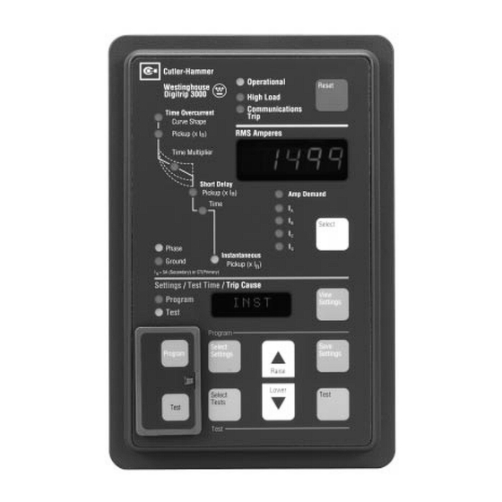
- Page 4 Digitrip 3000 Protective Relay (Front View)....................1 Digitrip 3000 Protective Relay (Rear and Side Views) ................2 A Digitrip 3000 Protective Relay Installed on a Metal Assembly Panel with a DP-4000 ......3 Digitrip 3000 Protective Relay with DIP Switches Shown in Upper Left (Rear View) ........3 Digitrip 3000 Curve Shape Possibilities.....................4...
- Page 5 Page Curve Selection ............................6 Characteristic for Phase Element ......................7 Characteristic for Ground Element ......................8 Miscellaneous Settings ..........................9 Factory Set Defaults ..........................10 Digitrip 3000 Curve Shapes........................18 Digitrip 3000 Display Messages ......................30 Digitrip 3000 Dip Switch Settings......................36 Troubleshooting Guide ..........................38 Effective 03/97...
-
Page 6: Section 1 Introduction
Digitrip 3000 Protective Relay. This document is provid- ed as a guide for authorized and qualified personnel COMPLETELY READ AND UNDERSTAND THE only in the selection and application of the Digitrip 3000 MATERIAL PRESENTED IN THIS DOCUMENT Protective Relay. Please refer to the specific WARNING BEFORE ATTEMPTING INSTALLATION, OPERATION and CAUTION in Section 1-1.2 before proceeding. -
Page 7: Functions/Features/Options
I = 5 amperes. It is operator configured shunt trip coil. Thermal curves, plus ANSI and IEC Figure 1-2 Digitrip 3000 Protective Relay (Rear and Side Views) Effective 03/97... -
Page 8: A Digitrip 3000 Protective Relay Installed On A Metal Assembly Panel With A Dp-4000
In the integral test Digitrip 3000 by setting pushbuttons located on the face- mode, a test current simulates an overload or short cir- plate of the relay. The phase and ground CT ratios can... -
Page 9: Digitrip 3000 Curve Shape Possibilities
With this vast selection of Curve Shapes, Digitrip 3000 phase to be disabled. When the Digitrip 3000 is not set provides protection capable of coordinating with most for an instantaneous trip function, a true making current any existing electro-mechanical overcurrent relay or release (discriminator) is available. -
Page 10: Standards
Figure 1-6 Installed Jumpers in Place on Terminal Block TB-1 Disabling the Zone Interlocking Feature 1-4 STANDARDS Digitrip 3000 Protective Relays are “Component ® Recognized” by the Underwriters Laboratory, Inc. under UL File E154862. Refer to Section 2-3 UL Testing and Specification Summary for more information. -
Page 11: Section 2: Functional Description
Extremely Inverse IEC-A Moderately Inverse 2-1.2 PICKUP SETTING IEC-B Very Inverse A Digitrip 3000 Protective Relay pickup setting is a dis- IEC-C Extremely Inverse crete, preselected value of current used to initiate a trip- IEC-D Definite Time ping action. The Digitrip 3000 has several current based tripping functions: •... -
Page 12: Characteristic For Phase Element
I.B. 17555 Page 7 Table 2.2 Characteristic for Phase Element TYPE SETTING AVAILABLE SETTINGS TOLERANCE CURVE # CURVE SHAPE IT, I T, I T, FLAT, MOD, VERY, XTRM, IECA, IECB, IECC, IECD INVERSE TIME OVERCURRENT 0.20, 0.25, 0.30, 0.35, 0.40, 0.45, 0.50, + 5% PICKUP 0.55, 0.60, 0.65, 0.70, 0.75, 0.80, 0.85,... -
Page 13: Characteristic For Ground Element
I.B. 17555 Page 8 Table 2.3 Characteristic for Ground Element TYPE SETTING AVAILABLE SETTINGS TOLERANCE CURVE # CURVE SHAPE IT, I T, I T, FLAT, MOD, VERY, XTRM, IECA, IECB, IECC, IECD INVERSE TIME OVERCURRENT 0.100, 0.125, 0.150, 0.175, 0.200, 0.225, + 5% PICKUP 0.250, 0.275, 0.300, 0.350, 0.400, 0.450,... -
Page 14: Miscellaneous Settings
I.B. 17555 Page 9 Table 2.4 Miscellaneous Settings TYPE SETTING AVAILABLE SETTINGS HIGHLOAD TIME 0 Sec, 5 Sec, 10 Sec, 30 Sec, 1 min, 2 min, 5 min, (pickup fixed @ 0.85 X Phase Time Overcurrent Setting) FREQUENCY 50 Hz, 60 Hz PHASE CT RATIO 5, 10, 25, 50, 75, 100, 150, 200, 250, 300, 400, 500, 600, 630, 800, 1000, 1200, 1250, 1500, 1600, 2000, 2400, 2500, 3000,... -
Page 15: 2-1.5 Integral Testing
PHASE SETTINGS 2-1.5 INTEGRAL TESTING Type Default Setting Curve Shape: Digitrip 3000 Protective Relays have a front accessible, integral field testing capability. This feature introduces a LDPU: selected level of internal test current to simulate an over- LDT: 5 sec. -
Page 16: Protective Relay Hardware
2-2 PROTECTIVE RELAY HARDWARE approximately 2-1/2 minutes. 2-2.1 FRONT OPERATIONS PANEL Note: Each Digitrip 3000 is shipped from the factory with nominal protection settings. The relay The operations panel, which is normally accessible from should be programmed by the user before being... -
Page 17: Typical Communications Wiring Diagram
- 150 OHM, 1/2 WATT FOR 1200 BAUD RATE COMMUNICATIONS. - 100 OHM, 1/2 WATT FOR 9600 BAUD RATE COMMUNICATIONS. A CUTLER-HAMMER CONI (COMPUTER OPERATED NETWORK INTERFACE) OR CONI-3 CARD MUST BE INSERTED INTO THE COMPUTER ISA BUS. CUSTOMER TO SUPPLY A COMPUTER AND MODULAR TELEPHONE CONNECTOR TYPE RJ11 AND WIRE PER VIEW A GROUND SHIELDING AT ONE PLACE ONLY (COMPUTER END RECOMMENDED). - Page 18 I.B. 17555 Page 13 Select Settings Pushbutton (Blue) functioning properly in its normal operation mode. If this In the program mode of operation, the Select Settings LED is blinking red, it indicates the relay may need pushbutton is used to step to the next setpoint by press- reprogramming.
-
Page 19: 2-2.2 Rear Access Panel
RMS Amperes DEATH. window. The rear access panel of Digitrip 3000 is normally accessi- LEDs ble from the rear of an open panel door (Figure 1-2). All The specific phase or ground current LEDs will be con-... - Page 20 Ampere” window until the “Reset” pushbutton is depressed. A RESET COMMAND can be sent to the Terminal 15 is the zone signal common. Zone common Digitrip 3000 by a master computer to remotely reset the should never be connected to earth ground. Digitrip 3000.
-
Page 21: 2-2.3 External Hardware
INCOM shield tie point. It is not connected to ground or tact. With DIP Switch S3 in the “on” position, this contact any electrical circuit in the Digitrip 3000. Terminals 4 and closes when the relay detects a need for the circuit 5 are a N.O. - Page 22 I.B. 17555 Page 17 2-3 UL TESTING AND SPECIFICATION SUMMARY (CONTINUED FROM PREVIOUS PAGE) CURRENT INPUTS: PHASE AND GROUND TIME-CURRENT CURVES: CT’s: 5 Amp Secondary Thermal: [Moderately Inverse] CT Burden: <0.004 ohm [Very Inverse] <0.1VA @ Rated Current(5A) [Extremely Inverse] I n : 5A(Secondary) or CT(Primary) FLAT...
-
Page 23: Section 3 Operation
(Per IEC 255-3) This section specifically describes the operation and Moderately Inverse IEC-A functional use of the Digitrip 3000 Protective Relay. It Very Inverse IEC-B does not address in detail rear power connections and DIP switch settings. These topics are covered in SEC-... -
Page 24: Digitrip 3000 Typical Wiring Diagram
I.B. 17555 Page 19 Figure 3-1 Digitrip 3000 Typical Wiring Diagram Effective 03/97... -
Page 25: Digitrip 3000 Time-Current Characteristic Curves
The effects of one set of settings a family of relays, like the Digitrip 3000. on another setting should always be evaluated to deter- mine if the results under all possible circumstances are The adjustability and continuous current of the Digitrip acceptable. -
Page 26: Sample Electronic Curves
I.B. 17555 Page 21 Note: Pickup and Tripping will occur within ±% of any selected trip point. (Pickup Accuracy) (Trip Point) (Trip Point) (Timing Accuracy) CURRENT CURRENT Typical Thermal Curve Typical ANSI and IEC Curves Figure 3-3 Sample Electronic Trip Curves The Time Multiplier setting is used to select a predeter- mined amount of time a sustained overload condition will be carried before the breaker trips. -
Page 27: Typical Time Multiplier Adjustment (I 2 T Response)
I.B. 17555 Page 22 Short Time Pickup Time Multiplier is is represented by represented by the the dotted portion dotted portion of of the curve. the curve. CURRENT CURRENT Figure 3-5 Typical Time Multiplier Adjustment (I Figure 3-6 Short Delay Setting Adjustment Response) the protective relay's trip relay is energized. -
Page 28: Typical Is Curve With I 2 T Slope
I.B. 17555 Page 23 Instantaneous pickup is represented by the Inverse Time Overcurrent dotted portion of the curve. SD Time Inverse SD Pick-up Inst. CURRENT CURRENT Figure 3-8 Typical Curve with I t Shape Figure 3-9 Instantaneous Setting Adjustment not take place at the expected time, if the Short Delay a number of protective functions, such as inverse time Time selected is in the higher end of time selection pos- overcurrent and short delay protection are combined... -
Page 29: 3-3.2 Program Mode
Program Mode pushbut- to determine if the overall desired result is obtained. For ton should be pressed and released to exit this reason, keep in mind the following Digitrip 3000 the Program Mode. selection possibilities and relay design features when programming the unit to closely coordinate with system 5. - Page 30 I.B. 17555 Page 25 ing that the Program Mode has been entered. The pre- the setting selected and the Select Settings pushbutton sent value of the first setpoint to be programmed (Curve is pressed and released, the Phase and Instantaneous Shape) will appear in the Settings/Test Time/Trip Cause LEDs remain on and the unit will now offer a choice of Window, which will be referred to as the Alpha-numeric...
-
Page 31: 3-3.3 Programming Overview
The flow chart entitled “Programming Sequence SHAPE GROUND CT RATIO Preview” (Figure 3-10) presents the general program- ming steps the Digitrip 3000 follows, always beginning with the “Curve Shape” selection. Each time the “Select Program the Settings” pushbutton is pressed and released, the relay GROUND INVERSE TIME advances to the next sequential step. -
Page 32: 3-3.4 Test Mode
(ERR) will appear and there will be an automatic exit The Digitrip 3000 Protective Relay has a built in INCOM from the Test Mode. This maximum current value can communication network port that is available on termi- be determined by multiplying 0.1 times the CT primary... -
Page 33: Local Programming Sequence Flow Chart
I.B. 17555 Page 28 Programming Notes: Open Circuit Breaker 1) New Settings can be saved individually at anytime during the Open Security Door programming process or in total at the end of the programming Program Mode LED Blinks Green and First process by pressing Press and Release “Program Setpoint’s Present Value (Phase Curve Shape) - Page 34 I.B. 17555 Page 29 Setting other than NONE If NONE Setting Selected To Change To Accept Setting Press “Select Settings” PB Short Delay Setting and Raise or Lower and Move to Ground Ground LEDs Blink Green Short Delay To Change To Accept Setting Short Delay Time or...
-
Page 35: Digitrip 3000 Display Messages
Digitrip 3000 tripped via the instantaneous function. “DISC” Digitrip 3000 tripped via the discriminator function. “EXTT” External trip via INCOM communications. “OVER” Override trip (Digitrip 3000 tripped via 100 per unit fixed instantaneous). “ORNG” Overrange value (trip value is greater than 28 per unit). Effective 03/97... -
Page 36: Section 4: Application Considera- Tions
I.B. 17555 Page 31 SECTION 4: APPLICATION CONSIDERA- When a Digitrip 3000 initiates a trip signal, the zone interlocking signal stays active for an additional 175 mil- TIONS liseconds. Therefore, if a downstream Digitrip 3000 is zone interlocked to an upstream Digitrip 3000, the... -
Page 37: Connection Diagram For Typical Phase Zone Selective Interlocking
BETWEEN FIRST AND LAST ZONE SHOULD BE 250 FEET. ROUTE SEPARATE FROM POWER CONDUCTORS. JUMPER ON DEVICES IN LAST ZONE USED TO PROVIDE TIME DELAY PER INVERSE TIME OVERCURRENT OR SHORT DELAY TIME SETTING. IF JUMPER NOT USED DIGITRIP 3000 WILL INITIATE TRIP WITHOUT TIME DELAY (NOMINALLY 0.1 SECONDS). -
Page 38: Connection Diagram For Typical Ground Zone Selective Interlocking
BETWEEN FIRST AND LAST ZONE SHOULD BE 250 FEET. ROUTE SEPARATE FROM POWER CONDUCTORS. JUMPER ON DEVICES IN LAST ZONE USED TO PROVIDE TIME DELAY PER INVERSE TIME OVERCURRENT OR SHORT DELAY TIME SETTING. IF JUMPER NOT USED DIGITRIP 3000 WILL INITIATE TRIP WITHOUT TIME DELAY (NOMINALLY 0.1 SECONDS). -
Page 39: Section 5: Installation, Startup And Testing
3-dimensional clearances for the relay chassis allow mounting in the desired location. The Digitrip 3000 can be installed as a direct replace- Digitrip 3000 Protective Relay dimensions are shown in ment for the Digitrip MV with proper DIP switch settings Figure 5-2. -
Page 40: Wiring
4. The Digitrip 3000 comes with zone interlocking jumpers installed (TB1 Terminals 11 to 12 and 13 to The wiring of the Digitrip 3000 Protective Relay must fol- 14). Depending on the application of zone interlock- low a suitable “wiring plan drawing.” The term wiring ing, these jumpers may have to be removed. -
Page 41: 5-5.2 Initial Power Application
I.B. 17555 Page 36 5-5.2 INITIAL POWER APPLICATION Table 5.1 Digitrip 3000 Dip Switch Settings Switch Positions a) Apply control power to the Digitrip 3000 Protective Switch Function Relay. Refer to Paragraph 3-2 entitled “Power-up And Self Testing.” IMPACC Buffers... -
Page 42: Section 6 Maintenance And Storage
6-1 GENERAL Step 1: Turn off control power at the main disconnect The Digitrip 3000 Protective Relay is designed to be a or isolation switch of the control power supply. self contained and maintenance free unit. The printed If the switch is not located in view from the... -
Page 43: Troubleshooting Guide
I.B. 17555 Page 38 Step 10: Restore control power. Refer to paragraphs 5- 4.2 entitled “Initial Power Application.” Table 6.1 Troubleshooting Guide (continued on next page) Symptom Probable Cause Possible Solution(s) Reference Operational LED is Off Protective Relay’s Control Verify that Control Power is Connected Figure 3-1 and Power is Deficient or Absent Between TB1-5 and TB1-6 and that it... - Page 44 Table 5.1 Check that “b” Contact is Operational Figure 5-3 Caution: When the Digitrip 3000 Protective Relay is Powered, it Supplies Voltage to the “b” Contacts Manual Reset Function Dip Switch S9 not set correctly Check DIP Switch Setting Table 5.1...
-
Page 45: Section 7 Time Current Curves
I.B. 17555 Page 40 SECTION 7: TIME-CURRENT CURVES 7-1 DIGITRIP 3000 INVERSE TIME OVERCURRENT CURVES The specific time-current curves applicable to the Digitrip 3000 Protective Relay are included in this sec- tion. Effective 03/97... -
Page 46: Curves (Sc-5390-92B)
I.B. 17555 Page 41 MULTIPLES OF I n VALUE 10000 10000 Adjustable Inverse Time Overcurrent Pickup (x I n ) (0.2 ..2.2) Adjustable Inverse Time Overcurrent Time Multiplier (Sec. @ 3 x I n ) (0.2 s ..40 s) Tolerance: 5000 5000... -
Page 47: Curves (Sc-5391-92B)
I.B. 17555 Page 42 MULTIPLES OF I n VALUE 10000 10000 Adjustable Inverse Time Overcurrent Pickup (x I n ) (0.2 ..2.2) Adjustable Inverse Time Overcurrent Time Multiplier (Sec. @ 3 x I n ) (0.2 s ..40 s) 5000 Tolerance: 5000... -
Page 48: Inverse Time Overcurrent Phase, It Curves (Sc-5392-92B)
I.B. 17555 Page 43 MULTIPLES OF I n VALUE 10000 10000 Adjustable Inverse Time Overcurrent Pickup (x I n ) (0.2 ..2.2) Adjustable Inverse Time Overcurrent Time Multiplier (Sec. @ 3 x I n ) (0.2 s ..40 s) 5000 Tolerance: 5000... -
Page 49: Inverse Time Overcurrent Phase, Flat Curves (Sc-5393-92B)
I.B. 17555 Page 44 MULTIPLES OF I n VALUE 10000 10000 Adjustable Inverse Time Overcurrent Pickup (x I n ) (0.2 ..2.2) Adjustable Inverse Time Overcurrent Time Multiplier (0.2 s ..2 s) Tolerance: Inverse Time Overcurrent Pickup is ±5% 5000... -
Page 50: Short Delay Phase Curves (Sc-5394-92B)
I.B. 17555 Page 45 MULTIPLES OF I n VALUE 10000 10000 Adjustable Short Delay Settings (x I n ) (1.0 ..11, None) Adjustable Short Delay Time (0.05 s ..1.5 s) Tolerance: Short Delay Setting is ±10% 5000... -
Page 51: Inverse Time Overcurrent/Short Delay Curves (Sc-5395-92B)
I.B. 17555 Page 46 MULTIPLES OF I n VALUE 10000 10000 Inverse Time Overcurrent Pickup = 1.0 x Inverse Time Overcurrent Time Multiplier = 10 s @ 3 x I n (I Short Delay Setting = 11 x Short Time Delay = 1.5 s 5000 5000 Note:... -
Page 52: Instantaneous Curves (Sc-5396-92B)
I.B. 17555 Page 47 MULTIPLES OF I n VALUE 10000 10000 Adjustable Instantaneous Trip (Phase Element) (1 ..25 x I n , None) Adjustable Instantaneous Trip (Ground Element) (0.5 ..11 x I n , None) Tolerance: Instantaneous Setting is ±10% 5000... -
Page 53: Curves (Sc-5399-92B)
I.B. 17555 Page 48 MULTIPLES OF I n VALUE 10000 10000 Adjustable Inverse Time Overcurrent Ground Pickup (x I n ) (0.1 ..2.0, None) Adjustable Inverse Time Overcurrent Time Multiplier Ground (Sec. @ 1 x I n ) (0.2 s ..40 s) 5000 5000 Tolerance:... -
Page 54: Curves (Sc-5400-92B)
I.B. 17555 Page 49 MULTIPLES OF I n VALUE 10000 10000 Adjustable Inverse Time Overcurrent Ground Pickup (x I n ) (0.1 ..2.0, None) Adjustable Inverse Time Overcurrent Time Multiplier Ground (Sec. @ 1 x I n ) (0.2 s ..40 s) 5000 5000 Tolerance:... -
Page 55: Inverse Time Overcurrent Ground, It Curves (Sc-5401-92B)
I.B. 17555 Page 50 MULTIPLES OF I n VALUE 10000 10000 Adjustable Inverse Time Overcurrent Ground Pickup (x I n ) (0.1 ..2.0, None) Adjustable Inverse Time Overcurrent Time Multiplier Ground (Sec. @ 1 x I n ) (0.2 s ..40 s) 5000 5000 Tolerance:... -
Page 56: Inverse Time Overcurrent Ground, Flat Curves (Sc-5402-92B)
I.B. 17555 Page 51 MULTIPLES OF I n VALUE 10000 10000 Adjustable Inverse Time Overcurrent Ground Pickup (x I n ) (0.1 ..2.0, None) Adjustable Inverse Time Overcurrent Time Multiplier Ground (0.2 s ..2 s) 5000 5000 Tolerance:... -
Page 57: Short Delay Ground Curves (Sc-5403-92B)
I.B. 17555 Page 52 MULTIPLES OF I n VALUE 10000 10000 Adjustable Short Delay Ground Settings (x I n ) (0.1 ..11, None) Adjustable Short Delay Time Ground (0.05 s ..1.5 s) Tolerance: Short Delay Setting is ±10% 5000... -
Page 58: Ansi Moderately Inverse Curves (Sc-6685-96)
I.B. 17555 Page 53 MULTIPLES OF PICKUP CURRENT (I/I pu ) 10000 10000 Adjustable Time Multiplier (0.1 ..5.0) Tolerance: Time Multiplier Tolerance is ±10% or ±0.09 s, whichever is larger 5000 5000 (>1.5 x I pu ) For Ground Pickup ≤0.2 pu : trip time tolerance is ±15% 2000 2000... -
Page 59: Ansi Very Inverse Curves (Sc-6686-96)
I.B. 17555 Page 54 MULTIPLES OF PICKUP CURRENT (I/I pu ) 10000 10000 Adjustable Time Multiplier (0.1 ..5.0) Tolerance: Time Multiplier Tolerance is ±10% or ±0.09 s, whichever is larger 5000 5000 (>1.5 x I pu ) For Ground Pickup ≤0.2 pu : trip time tolerance is ±15% 2000 2000... -
Page 60: Ansi Extremely Inverse Curves (Sc-6687-96)
I.B. 17555 Page 55 MULTIPLES OF PICKUP CURRENT (I/I pu ) 10000 10000 Adjustable Time Multiplier (0.1 ..5.0) Tolerance: Time Multiplier Tolerance is ±10% or ±0.09 s, whichever is larger 5000 5000 (>1.5 x I pu ) For Ground Pickup ≤0.2 pu : trip time tolerance is ±15% Minimum Trip Time is 2 power line cycles 2000... -
Page 61: Iec-A Moderately Inverse Curves (Sc-6688-96)
I.B. 17555 Page 56 MULTIPLES OF PICKUP CURRENT (I/I pu ) 10000 10000 Adjustable Time Multiplier (0.05 ..1.00) Tolerance: Time Multiplier Tolerance is ±10% or ±0.09 s, whichever is larger 5000 5000 (>1.5 x I pu ) For Ground Pickup ≤0.2 pu : trip time tolerance is ±15% 2000 2000... -
Page 62: Iec-B Very Inverse Curves (Sc-6689-96)
I.B. 17555 Page 57 MULTIPLES OF PICKUP CURRENT (I/I pu ) 10000 10000 Adjustable Time Multiplier (0.05 ..1.00) Tolerance: Time Multiplier Tolerance is ±10% or ±0.09 s, whichever is larger 5000 5000 (>1.5 x I pu ) For Ground Pickup ≤0.2 pu : trip time tolerance is ±15% Minimum Trip Time is 2 power line cycles 2000... -
Page 63: Iec-C Extremely Inverse Curves (Sc-6690-96)
I.B. 17555 Page 58 MULTIPLES OF PICKUP CURRENT (I/I pu ) 10000 10000 Adjustable Time Multiplier (0.05 ..1.00) Tolerance: Time Multiplier Tolerance is ±10% or ±0.09 s, whichever is larger 5000 5000 (>1.5 x I pu ) For Ground Pickup ≤0.2 pu : trip time tolerance is ±15% Minimum Trip Time is 2 power line cycles 2000... -
Page 64: Iec-D Flat Curves (Sc-6691-96)
I.B. 17555 Page 59 MULTIPLES OF PICKUP CURRENT (I/I pu ) 10000 10000 Adjustable Time Multiplier (0.05 ..1.00) Tolerance: Time Multiplier Tolerance is ±0.05 s 5000 5000 2000 2000 1000 1000 Time Multiplier 1000 MULTIPLES OF PICKUP CURRENT (I/I pu ) Figure 7-19 IEC-D Flat Curves (SC-6691-96) Effective 03/97... -
Page 65: Digitrip 3000 Curve Equations
I.B. 17555 Page 60 7-2 DIGITRIP 3000 CURVE EQUATIONS Low Voltage Breaker Curve Equation T = Trip Time SLOPE D = Time Multiplier (0.2 to 40) D * K I = Input Current M = Slope (0 = FLAT, 1 = IT, 2 = I... - Page 66 ING OR USAGE OF TRADE, ARE MADE REGARDING THE INFORMATION, RECOMMENDATIONS AND DESCRIPTIONS CONTAINED HEREIN. In no event will Cutler-Hammer be responsible to the purchaser or user in contract, in tort (including negligence), strict lia- bility or otherwise for any special, indirect, incidental or...
Need help?
Do you have a question about the Digitrip 3000 and is the answer not in the manual?
Questions and answers