Table of Contents
Advertisement
Advertisement
Table of Contents

Related Manuals for OrangeRx TX6i


Summary of Contents for OrangeRx TX6i
- Page 1 INSTRUCTION MANUAL 6 CHANNEL TRANSMITTER...
-
Page 2: Safety Guide
Introduction Thank you for purchasing our product, an ideal radio system for beginners or experienced users alike. Read this manual carefully before operation in order to ensure your safely and the safely of others or the safe operation of your system. If you encounter any problem persists, contact your www.hobbyking.com local deal or visit our service and support website for Safely... -
Page 3: Fcc Statement
Do not touch any part of the model that may generate heat during operation. The engine, motors and speed control may be hot and cause injury. Do not grasp the transmitter’s antenna during flight. It may be degraded the quality of the radio frequency transmission. -
Page 4: Transmitter Overview
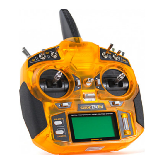
Transmitter Overview Lanyard hook Throttle/Rudder Elevator/Aileron Trim Trim Trim Trim Binding key Wheel Cancel key Antenna Handle Trainer port Grip Bettery compartment Installation and removal of the transmitter battery The T6i transmitter is designed to work with four x (LR6) AA alkaline dry cell batteries 6 CHANNEL TRANSMITTER DIGITAL PROPORTIONAL RADIO CONTROL SYSTEMPROGRAMABLE SYSTEM... -
Page 5: Binding Procedure
Push Push and slide down and slide down Battery cover Binding procedure (Take ORX receiver as example) 1. Install a bind plug into BIND connector. In case if you want to disable telemetry function on the receiver, install second bind plug into THRO connector. 2. -
Page 6: Servo Setup
5. The system will display “RX Binding..”. After successfully binding, the transmitter will automati cally exit this binding menu. 6. Remove the bind plug(s) from the BIND on the receiver NOTICE: Remove the bind plug to prevent the system from entering bind mode the next time the power is turned on. -
Page 7: End Points
End points End points controls the low and high travel limits for each servo. For each channel the user can set the low and high limits. This ensures that the channel date for the servo is consistent with structur- al design and performance requirements to ensure the best results. Adjustment can be made for any channel. -
Page 8: Throttle Curve
Dual rate/exp. This function is use to add a curve to the channels input. This means that the ratio of stick to channel movement can be changed in order to add or remove sensitivity at different parts of the sticks range of motion. It can available on the aileron, elevator and rudder channels. This function sets the rate and exp. -
Page 9: Throttle Cut
Setup: 1. Select “Throttle Curve” in main menu 2. Press the Roller button to select point L, 1, 2, 3, H. 3. Move the wheel left or right to change the point’s value (position) on the graph. 4. Press and hold the wheel to save an exit 5. -
Page 10: Range Test
Mixes This function is used to create a mix between channels. For example, if at low throttle some auto- mated flap movement is desired, it is possible to create a mix to do this. The difference between curve mixes and linear mixes is that it is no possible to create a nonlinear relationship between the master and slave. - Page 11 2.Press and hold the Binding key to activate Range test Timer This function is used to keep track of time to reduce the risk of aircraft running out of battery/fuel and crashing. These are very useful when used in conjunction with a toggle. There are two choices for timer: Engine timer and Multi.
- Page 12 Up Mode: Reset - Press and hold the cancel key to reset the timer if needed, then press the Roller button Thr. pos - Turn the Roller button to change the throttle trigger point. Press and hold the Roller button to save an exit or press the cancel key to exit without saving Down Mode: Reset - Press and hold the cancel key to reset the timer if needed, then press the Roller button...
-
Page 13: Setup Sensors
Reset Switch – Turn the Roller Button to reset the switch 1 to 8 or None to position up, mid or down Press and hold the Roller button to save an exit or press the cancel key to exit without saving Down and up Mode: Timer State –... - Page 14 This setting is used to sound an alarm when the receiver battery voltage drops dangerously low Batt: This setting is used to sound an alarm when the voltage out of range Temp: Temperature information is came from an optional Temperature sensor. If it becomes higher or lower than the settling, an alarm will alert you Current information is came from a optional Current sensor.
-
Page 15: Aux. Channels
Aux. channels This function allows users to set auxiliary channels. Every channel that is not assigned during the model setup will be set as an AUX channel. AUX channels can be used to control various extra features on an aircraft including landing gear, brakes, lights. Setup: 1. -
Page 16: Model Setup
Model setup The mode setup function is used to set up, manage and delete models. Model Select: Selects a model from memory. 1. Use the wheel to select a memory slot for the model. 2. Press and hold the wheel to save an exit, or press the cancel key to exit without saving. Type select: Change between airplane/glider and different helicopter types and multicopter. -
Page 17: Model Reset
Model Reset: Resets a model to factory default settings. 1. Use the wheel to select a memory slot for the model. 2. Press the wheel to select and then move the wheel to select yes and press the wheel again. 3. - Page 18 Elevon: The elevon function is used for planes that combine the elevens an ailerons together. Setup: 1. Use the wheel to enable the elevon function and press the wheel. 2. Use the wheel to set the first channels position and press the wheel. 3.
-
Page 19: Pitch Curve
3. If needed set the flaperon to a switch using the wheel then press the wheel. 4. Choose the flaperon position. 5. Press and hold the wheel to save an exit, or press the cancel key to exit without saving. Bind: The transmitter and receiver have been pre-bound before delivery. - Page 20 Model setup Swashplate mix Adjust the motion range of these three functions to achieve the desired maneuverability. Refer to your models manual to ensure best results. This function is used to edit the pre-programmed mix control of the helicopter’s aileron, elevator and pitch.
-
Page 21: System Setup
The function ensures a model will not fly until a switches has been toggled. Setup: 1. Use the wheel to select a switch or on, then press the wheel. 2. Use the wheel to select a channel. 3. Press and hold the wheel to save an exit, or press the cancel key to exit without saving. System setup User name Set a username for your system. -
Page 22: Student Mode
Student mode This function is used when another system is connected as a master (trainer), when this mode is active all settings will be bypassed and the system will only function through the master. Press and hold the wheel and move the wheel to select yes. Sticks mode There are 4 available stick modes, each stick mode changes the stick functions. -
Page 23: System Settings
System settings Firmware Ver. This function shows information about the transmitters currently installed firmware version. Firmware update The function is for updating the system firmware. Setup: www.hobbyking.com 1. Download the latest firmware from 2. Open the firmware update on a computer and connect the system via USB cable. 3. -
Page 24: Factory Reset
RF module update This function is for updating the RF module. Setup: 1. Connect the system via USB cable. 2. Press the wheel, the system will show a prompt, “ This will enter RF module update mode and halt other functions” with an option to continue, Select “Yes”. 3.
Need help?
Do you have a question about the TX6i and is the answer not in the manual?
Questions and answers
what is the usb slot for under the buddy lead connection