Table of Contents
Advertisement
Advertisement
Table of Contents

Related Manuals for AGD 318


Summary of Contents for AGD 318
- Page 1 AGD 318 TRAFFIC CONTROL RADAR AGD 318 TRAFFIC CONTROL RADAR PRODUCT MANUAL ✓...
-
Page 2: Table Of Contents
Table of Contents AGD 318 TRAFFIC CONTROL RADAR AGD 318 INTRODUCTION INSTALLATION - SERIAL COMMS VARIANT TRAFFIC CONTROL RADAR Product & technology Radar installation and alignment Key features FIRMWARE FUNCTIONALITY Typical applications Overview (Serial comms unit only) Product overview RADAR PERFORMANCE - SERIAL COMMS UNIT ONLY... -
Page 3: Introduction
The radars‘ advanced detection algorithms make it suitable for both urban and inter-urban detection applications. The 318 radar is a frequency modulated continuous wave, FMCW, radar that operates in the 24GHz band. KEY FEATURES • Speed measurement from 4 kph to 300 kph across multiple lanes (depending on variant) •... -
Page 4: Typical Applications
Introduction AGD 318 TRAFFIC CONTROL RADAR TYPICAL APPLICATIONS AGD 318 TRAFFIC CONTROL RADAR Sign activation Multi-lane highway via comms output Single lane detection for traffic control Dual line detection for rail Wrong direction detection for highways... -
Page 5: Product Overview
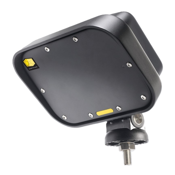
Introduction AGD 318 TRAFFIC CONTROL RADAR PRODUCT OVERVIEW AGD 318 The product is available in a number of build variants with different operating voltages and output currents. TRAFFIC CONTROL RADAR Front (Power On) Detect LED Pan and Tilt Mounting Foot... -
Page 6: System Hardware Overview
System Hardware Overview AGD 318 TRAFFIC CONTROL RADAR SYSTEM HARDWARE OVERVIEW AGD 318 TRAFFIC CONTROL RADAR Target Simulator Microwave (Hardware Build Transceiver Option) Amplifiers & Signal Modulation Conditioning Analogue to Digital Converter Digital Signal Processor Primary Secondary Comms Switched Switched... -
Page 7: Radar Characteristics
Radar Characteristics AGD 318 TRAFFIC CONTROL RADAR The radar has been designed to have a specific set of functional AGD 318 characteristics which make it suitable for range & speed measurements of multiple targets. TRAFFIC CONTROL RADAR RADAR ANTENNA The antenna design is a planar patch array with the following performance;... -
Page 8: Frequency Variants
Licence Required for Use Frequency Allocated but EIRP too high It is important to note that this table is updated from time to time. Please contact AGD for latest information if your intended country of use is not currently represented. -
Page 9: Antenna Plots
Radar Characteristics AGD 318 TRAFFIC CONTROL RADAR ANTENNA PLOTS AGD 318 TRAFFIC CONTROL RADAR Angle (Degrees) Horizontal Beam Pattern Vertical Beam Pattern... -
Page 10: Opto Variants
Important Opto Variants AGD 318 TRAFFIC CONTROL RADAR OVERVIEW AGD 318 Available as simple single opto output or as dual opto output with added functionality. TRAFFIC CONTROL RADAR POWER & CONNECTIONS - 12VDC/24VAC/DC - SINGLE OPTO OUTPUT 12Vdc/24Vac/dc - Bulgin connector or 5m flying lead The output is an SPCO (SPDT) Opto with the impedance state of the relay being the same for a detect state or power off condition. -
Page 11: Power & Connections - 230Vac Single Relay Output
The detector is supplied with two 5m flying leads. One is the power supply for the detector and the other is the signal output and the correct cables should be identified before connection. The 318 is classified as a double insulated product and therefore the supply cable is two core (live/neutral). -
Page 12: Power & Connections - 230Vac - Dual Relay Output
Opto Variants AGD 318 TRAFFIC CONTROL RADAR POWER & CONNECTIONS - 230VAC - DUAL RELAY OUTPUT AGD 318 230Vac - 5m flying lead TRAFFIC CONTROL RADAR Twin Cable 230Vac Supply Wiring (5m flying lead) Cable Wire Colour Function Power Off... -
Page 13: Mounting Height, Angles, Clearance
Installation AGD 318 TRAFFIC CONTROL RADAR MOUNTING HEIGHT, ANGLES, CLEARANCE AGD 318 Mount the radar on a firm structure within a recommended height range of 2m-5m. For optimum performance TRAFFIC CONTROL RADAR the radar should be situated on a pole adjacent to the carriageway with an unobstructed view of advancing traffic. -
Page 14: Configuration
2) Launch the software from your Desktop/Start menu by clicking the 318 Livewire icon. - The application will search for all 318 detectors within range and will display these once discovered 3) Select the desired 318 unit from the list and click continue. - Page 15 Configuration SINGLE OPTO USER INTERFACE Radar Detection Zone (red dotted area) Opto Activation Zone 1 Opto Activation Sensitivity Detection Speed Output Status Zone Adjustment Adjustment Adjustment SETTINGS SUMMARY Item Description Note No.of Outputs One Opto-Isolator Low Range Threshold 6 - 70m Default 6m High Range Threshold 6 - 70m...
- Page 16 Configuration DUAL OPTO USER INTERFACE Radar Detection Zone (red dotted area) Opto Activation Zone 2 Opto Activation Zone 1 Opto Activation Upper & Lower Detection Zone 2 Zone 1 Zone 2 Zone 1 Zone Adjustments Sensitivity Speed Config Config Status Status Adjustment Adjustment...
-
Page 17: Detection Zone Set-Up
Configuration AGD 318 TRAFFIC CONTROL RADAR DETECTION ZONE SET-UP AGD 318 An important part of the set-up and configuration of the radar are the three items highlighted in the window below. TRAFFIC CONTROL RADAR There are three components to this window: The ‘direction filter’... -
Page 18: Opto Activation Zone 1 (Or 2) Configuration Parameters
Configuration Configuration AGD 318 TRAFFIC CONTROL RADAR OPTO ACTIVATION ZONE 1 (OR 2) CONFIGURATION OPTO ACTIVATION ZONE 1 (OR 2) CONFIGURATION AGD 318 PARAMETERS PARAMETERS TRAFFIC CONTROL RADAR Function of the settings in the OPTO activation zone 1 (or 2) windows, when ‘Vehicle Detect Output’ is selected: Function of the settings in the OPTO activation zone 1 (or 2) windows, when ‘Vehicle Detect Output’... - Page 19 Configuration AGD 318 TRAFFIC CONTROL RADAR OPTO ACTIVATION ZONE 1 (OR 2) CONFIGURATION AGD 318 PARAMETERS TRAFFIC CONTROL RADAR Function of the settings in the OPTO activation zone 1 (or 2) windows, when ‘Output Type: Disabled’ is selected: ‘Disabled’ – The output is disabled and performs no function Function of the settings in the OPTO activation zone 1 (or 2) windows, when ‘Output Type: Heartbeat’...
-
Page 20: Connecting (Wifi Version)
TRAFFIC CONTROL RADAR AGD 318 The AGD 318 Traffic Control Radar has been designed with efficiency and ease of use in mind. It is connected to, TRAFFIC CONTROL RADAR using a WiFi enabled device (laptop, tablet or phone) and setup simply using a browser window. -
Page 21: Wifi User Interface
Important Configuration WiFi USER INTERFACE Radar Zone 1 Detection Status Zone (red dotted area) Opto Zone 2 Activation Status Zone 1 Opto Activation Zone 2 Opto Activation Upper & Lower Detection Zone 2 Zone 1 Zone Adjustments Sensitivity Speed Config Config Adjustment Adjustment... -
Page 22: Detection Zone Set-Up (Wifi Version)
Important Configuration AGD 318 TRAFFIC CONTROL RADAR DETECTION ZONE SET-UP (WIFI VERSION) AGD 318 An important part of the set-up and configuration of the radar are the three items highlighted in the window below. TRAFFIC CONTROL RADAR There are three components to this window: The ‘direction filter’... -
Page 23: Opto Activation Zone 1 (Or 2) Configuration Parameters (Wifi Version)
Important Configuration AGD 318 TRAFFIC CONTROL RADAR OPTO ACTIVATION ZONE 1 (OR 2) CONFIGURATION AGD 318 PARAMETERS (WIFI VERSION) TRAFFIC CONTROL RADAR Function of the settings in the OPTO activation zone 1 (or 2) windows, when ‘Vehicle Detect Output’ is selected: ‘Vehicle Detect Output’... - Page 24 Important Configuration AGD 318 TRAFFIC CONTROL RADAR OPTO ACTIVATION ZONE 1 (OR 2) CONFIGURATION AGD 318 PARAMETERS (WIFI VERSION) TRAFFIC CONTROL RADAR Function of the settings in the OPTO activation zone 1 (or 2) windows, when ‘Output Type: Disabled’ is selected: ‘Disabled’...
-
Page 25: Queue Detection Operation (Wifi Version)
Important Configuration AGD 318 QUEUE DETECTION OPERATION (WIFI VERSION) TRAFFIC CONTROL RADAR AGD 318 TRAFFIC CONTROL RADAR Queue Detection Parameters Loop Position: • Defines the position at which a queue is detected Queue Range Limits: • Limits the range over which the queue function searches for tracked targets. -
Page 26: Traffic Control Radar
Configuration AGD 318 QUEUE DETECTION OPERATION (WIFI VERSION) TRAFFIC CONTROL RADAR AGD 318 Queue Detection Mode Operation TRAFFIC CONTROL RADAR The queue detection mode is used to hold an output on when traffic has ‘queued’ back to a certain point. -
Page 27: Rs422 Variant (Serial Comms Unit)
Communications can be established to the Serial Comms version TRAFFIC CONTROL RADAR of the AGD 318 Radar by using the CA-250 cable assembly or a third party USB to RS422 Converter. A UART interface is provided that uses RS422 voltage levels on the communications connector. -
Page 28: Radar Installation And Alignment
System Integration The 318 has been designed to output a target message stream when a target is detected by the radar. When there is no target only the heartbeat message will be sent (if turned on). The radar is designed to send data and not make decisions on incidents that may be specified. -
Page 29: Firmware Functionality
Firmware Functionality AGD 318 TRAFFIC CONTROL RADAR OVERVIEW (SERIAL COMMS VERSION ILLUSTRATED) AGD 318 At power-on the radar executes a Boot-loader program which communicates at a fixed Baud rate of 115200, no TRAFFIC CONTROL RADAR parity, 8 data bits and 1 stop bit over the RS422 interface. The Boot-loader provides facilities for erasing the Flash and updating the firmware. -
Page 30: Radar Performance - Serial Comms Unit Only
TRAFFIC CONTROL RADAR A series of radar techniques have been used in the 318 to maximise the signal to noise ratio for a given target. The range performance of the 318 is tested at manufacture by simulation to ensure operation over the range 6 to 70m. -
Page 31: Radar Command Overview
Radar Commands - Serial Comms Unit Only AGD 318 TRAFFIC CONTROL RADAR RADAR COMMAND OVERVIEW AGD 318 Commands are used to control the operation of the radar. These are sent over the RS422 UART link. TRAFFIC CONTROL RADAR Commands are immediately followed by an operator that indicates the required action. Not all operators are supported for all commands. -
Page 32: Radar Command List
Radar Commands - Serial Comms Unit Only AGD 318 TRAFFIC CONTROL RADAR RADAR COMMAND LIST AGD 318 Command Type Function Default Value Min Units, Resolution or TRAFFIC CONTROL RADAR Value Value Values Provides the firmware version *ANGLE ?/=/^ Enquire / set the radar mounting angle 22.0... - Page 33 Radar Commands - Serial Comms Unit Only AGD 318 TRAFFIC CONTROL RADAR RADAR COMMAND LIST (CONTINUED) AGD 318 Command Type Function Default Units, Resolution or Values TRAFFIC CONTROL RADAR Value Value Value *ETPnLPT ?/=/^ Enquire / Set the optional Event Trigger Point Low...
-
Page 34: Ts Command & Hardware Self-Test (Option)
Radar Commands - Serial Comms Unit Only AGD 318 TRAFFIC CONTROL RADAR *TS COMMAND & HARDWARE SELF-TEST (OPTION) AGD 318 This function is a hardware build option. TRAFFIC CONTROL RADAR The radar has a built in hardware based target simulator. This command is used to perform a self-test using this built in target simulation hardware. - Page 35 Radar Commands - Serial Comms Unit Only AGD 318 TRAFFIC CONTROL RADAR *TS COMMAND & HARDWARE SELF-TEST (CONTINUED) AGD 318 When in Advance Mode the radar will only accept and report simulated targets that are advancing. If a recede TRAFFIC CONTROL RADAR simulated target is requested the radar processing will reject the target as ‘wrong direction’...
-
Page 36: Message Formats - Serial Comms Unit Only
Message Formats - Serial Comms Unit Only AGD 318 TRAFFIC CONTROL RADAR TARGET DETECT MESSAGE AGD 318 Target Detect Message TRAFFIC CONTROL RADAR This message is sent after the radar has established that a vehicle has entered the radar’s beam. -
Page 37: Event Trigger Point Message
Message Formats - Serial Comms Unit Only AGD 318 TRAFFIC CONTROL RADAR EVENT TRIGGER POINT MESSAGE AGD 318 Event Trigger Point Message TRAFFIC CONTROL RADAR This message is sent when a target passes a defined Event Trigger Point. The Event Trigger Point is defined with the ‘*ETPn’... -
Page 38: Radar Event Message
Message Formats - Serial Comms Unit Only AGD 318 TRAFFIC CONTROL RADAR RADAR EVENT MESSAGES AGD 318 Heart Beat message TRAFFIC CONTROL RADAR This message is sent each time the heart period expires. The heart beat message period is controlled using the *HBP command. -
Page 39: Checksum Configuration
CHECKSUM CALCULATION AGD 318 The unsolicited messages and the Serial Number output by the 318 contain a checksum. The checksum is TRAFFIC CONTROL RADAR performed as an exclusive OR (XOR) sum of each of the characters in the message excluding the header and termination characters. -
Page 40: Updating Application Code
• Configure a terminal communications port to a baud rate of 115200, No Parity, 8 data bits and 1 stop bit. AGD recommends using RealTerm as this allows delays to be inserted after End of Line transmissions. • Power on the radar with the comms cable attached to the PC. The Bootloader version information is displayed and a countdown is started to boot the main application. - Page 41 TRAFFIC CONTROL RADAR UPDATING APPLICATION CODE AGD 318 • Send the application file over the port. AGD recommends inserting a delay of 1ms between each line as TRAFFIC CONTROL RADAR shown in the following screen-shot File to Codeload 1mS delay •...
- Page 42 • Change the BAUD rate for the main application to 460800, ODD parity, 8 data bits and 1 stop bit (if using TRAFFIC CONTROL RADAR RealTerm you need to hit the ‘Change’ button after changing the settings. • Type AGD to confirm the code version...
-
Page 43: Technical Specifications
ETSI 300.440, FCC CFR47 Part 15.245* MTBF 20 years *For US special build variant required Owing to the Company’s policy of continuous improvement, AGD Systems Limited reserves the right to change their specification or design without notice. RoHS Registration Evaluation... -
Page 44: Manufacturing Test Process
The test results in association with the product build revision are recorded on a product serial number basis. The full suite of test measurements is instantly sent to the dedicated product database within the AGD secure server facility, providing full traceability during the product lifetime. -
Page 45: End Of Life - Disposal Instructions (Eol)
End Of Life – Disposal Instructions (EOL) AGD 318 TRAFFIC CONTROL RADAR AGD318 RADAR TRAFFIC DETECTOR AGD 318 TRAFFIC CONTROL RADAR • Reuse / Recycle Item Qty Material Item Qty Material • Nylon Printed Circuit Board Steel Electronic Assy Separate & Recycle •... -
Page 46: Safety Precautions
Under no circumstances should a product suspected of damage be powered on. Internal damage may be suggested by unusual behaviour, an unusual odour or damage to the outer casing. Please contact AGD for further advice. -
Page 47: Low Power Non-Ionising Radio Transmission And Safety
0.318mW/cm2) is at a point in the field where the radar beam is not properly formed. Note 4 Comparison for product model 318 operating in the band typically 24.050GHz to 24.250GHz From the table it can be seen that it is extremely unlikely that a potentially hazardous situation could occur owing to the use of such low power devices. -
Page 48: Certificates
Certification... - Page 49 Notes...
- Page 50 Notes...
- Page 51 Notes...
-
Page 52: Disclaimer
Disclaimer While we (AGD Systems) endeavour to keep the information in this manual correct at the time of print, we make no representations or warranties of any kind, express or implied, about the completeness, accuracy, reliability, suitability or availability with respect to the information, products, services, or related graphics contained herein for any purpose.
Need help?
Do you have a question about the 318 and is the answer not in the manual?
Questions and answers