
Summary of Contents for TECNORD RC-PCM
- Page 1 RC-DBM/PCM/NBM Radio Remote Control Systems Use and Maintenance Manual TECNORD SERVOCOMANDI E REGOLAZIONE...
- Page 2 All reproduction rights, either through photocopies or computer means or supports, are reserved. All texts, illustrations, and drawings are the propriety of TECNORD and their use can only be granted prior to the formal permission of TECNORD.
-
Page 3: Table Of Contents
Safety Measures to be taken within the working area_________________________________________ 4 Protection Devices______________________________________________________________________ 4 How to react and behave in case of an Emergency ___________________________________________ 4 RC-DBX, RC-PCM SYSTEM’S COMPONENTS _________________________________________________ 5 Transmitter Unit Control Configurations __________________________________________________ 5 INSTALLATION ___________________________________________________________________________ 7... -
Page 4: Safety
Each Radio Control should be checked at least once per year. Any repair should be made at authorized centers or centers that Tecnord has recommended or directly at the Tecnord service and spare parts center. Any use of no-original spare parts or tampering by non-authorized staff immediately cancels all the warranty rights. -
Page 5: Rc-Dbx, Rc-Pcm System's Components
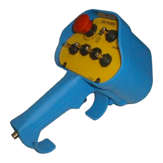
4 / 5 / 6 RC-DBM 4 / 5 / 6 RC-PCM transmitters (PCJ-TX) are designed for systems with multiple proportional actuators. The control configuration therefore varies with the number of joysticks provided. Standard equipped actuators are shown in the figure below. JLP joysticks... - Page 6 TECNORD RC-NBM transmitters (NBJ-TX) are designed for systems with multiple proportional actuators. The control configuration therefore varies with the number of joysticks provided. Standard equipped actuators are shown in the figure below. Connector for battery charging and cable communication Pushbutton for...
-
Page 7: Installation
TECNORD declines all responsibility, neither does it grant any guarantee whatsoever for any damage caused to things or persons due to the improper or careless use of this equipment or due to the non-observance of any regulation or that, which has been indicated in the operating instructions. -
Page 8: Pcj Transmitter Unit Sample Drawing
TECNORD DBD/DBR control configurations DBM control configuration PCJ Transmitter Unit sample drawing PCM control configuration NBJ Transmitter Unit sample drawing NBM control configuration RC-DBX/PCM/NBM Use and Maintenance Manual Page 8/23... -
Page 9: Battery Charger And Serial Cable Sample Drawings
TECNORD Battery Charger and Serial Cable sample drawings M12 connector M12 connector M12 connector plug SERIAL CABLE BATTERY CHARGER CABLE Outside electrical connections Outside electrical connections are: Power Supply Input / Output connections For safety reasons it is recommended to install on the controlled machine a supply disconnecting device in order to cut off the receiver’s power supply when necessary. -
Page 10: Declaration Of Installation
Emergency Stop function. TECNORD is not responsible of the remore control’s installation; the installer is therefore required to issue the operator a Declaration of Installation that must be kept together with this manual by the operator. A template for the declaration of Installation is shown below. -
Page 11: Operation
The radio transmission and servicing system Tecnord’s RC-DBX ,RC-PCM and RC-NBM Radio Control Systems allow for the operating machines to be controlled in general by means of electro-magnetic waves. It is made up of a portable transmitter unit (SHW ,PCJ TX or NBJ-TX) held by the operator and of a receiver unit (DBX-RX) that is usually installed on the machine to be controlled. -
Page 12: Visual Check
Release the Emergency Stop Push Button on the Transmitter unit, if pressed. Releasing the Emergency Stop Push Button turns the TX unit on. In RC-PCM or RC-NBM systems it is necessary to engage the radio control with the appropriate pushbutton. -
Page 13: Diagnostics
The non-operation of an RC-DBX , RC-PCM , RC-NBM system may depend on either the transmitter or the receiver. The table located in the following paragraph may help in the diagnosis of the most common causes of malfunction. -
Page 14: Maintenance
5 MAINTENANCE Tecnord’s RC-DBX,RC-PCM,RC-NBM Radio Control Systems does not require any special maintenance. However, some precautions are necessary in order to ensure that the equipment is both efficient and safe. Each radio control must be checked at least once a year. -
Page 15: Technical Data
TECNORD 7 TECHNICAL DATA Transmitter (SHW-TX, PCJ-TX,NBJ-TX) USA/CANADA version EUROPE version Working frequency: 902 ÷ 928 MHz 869.7 ÷ 870 MHz Transmission Type: FHSS (Frequency Hopping Spread Spectrum) Single Frequency FSK RF output power: < 200 mW e.r.p. < 5 mW e.r.p... -
Page 16: System Diagnostics And Configuration
TECNORD SYSTEM DIAGNOSTICS AND CONFIGURATION Transmitter’s Diagnostics Diagnistic on the Transmitter unit is carried out by means of: a buzzer a green led 8.1.1 Buzzer Indications in Radio Mode: The buzzer provides the following indications: one short beep when the Transmitter is powered on, i.e. when the Emergency Stop Pushbutton is released;... -
Page 17: Normal Display Menu
TECNORD 8.2.2 Normal Display Menu This is the menu for the normal operating mode, and is selected by default when the Receiver is powered on. The following indications are displayed: Normal operation: No active operation No active operation No active operation... -
Page 18: Current Display Menu
TECNORD The following table shows all the displayed codes: Displayed code for Microswitch open Displayed code for Microswitch closed Displayed Digital Input When no operation is activated the Receiver automatically switches to the Normal Display Menu after 60s, otherwise a new power- on is required in order to get out of this menu. -
Page 19: Calibration Menu
TECNORD Calibration Menu This paragraph is applicable only to systems that implement a proportional current output. The calibration of the parameters of the proportional output is carried out using the two Pushbuttons (Blue Key and Yellow Key) integrated in the receiver’s electronics, shown in the figure below. -
Page 20: Calibration Parameters For Dbm / Pcm / Nbm Systems
The only way to exit from this menu is a new power-on of the Receiver (i.e. disconnecting the power supply from the receiver). RC-PCM systems allow to select between two speed sets (normal and reduced working speed), allowing to independently adjust each parameter of every semi-function in every single speed set. Just select in the Transmitter... -
Page 21: System Menu (For Trained Staff Only)
ZERO System Menu (for trained staff only) The System Menu allows basic configurations of the RC-DBX , RC-PCM and RC-NBM systems; depending on the system, the configuration process involves different steps, which are organized as submenus. For RC-DBD/DBR systems the sequence of submenus is: Proportional Trigger Acquisition (only useful for DBR, only available with the Service Cable connected). -
Page 22: Proportional Trigger Acquisition
TECNORD Instructions for the system menu setup: Disconnect the power supply from the receiver unit. Keep the Receiver’s electronics outside its enclosure in order to access the two pushbuttons: Blue Key (B-KEY) and Yellow Key (Y- KEY). Keeping both pushbuttons (B-KEY and Y-KEY) pressed, power the receiver on. After the initialization phase, the unit enters the System Menu. -
Page 23: System Type Setup
Analog Voltage Output Range Setup This parameter specifies which kind of system is driven by the analog voltage outputs of an RC-DBM , RC-PCM or RC-NBM system. Its value affects the voltage values displayed during parameters adjustments and tells the system if the output voltage must be an absolute value or ratiometric with respect to the measured battery voltage.
Need help?
Do you have a question about the RC-PCM and is the answer not in the manual?
Questions and answers