Table of Contents
Advertisement
INSTALLATION & OPERATING
MAXUS DIRECT VENT HEATER LISTED GAS APPLIANCE
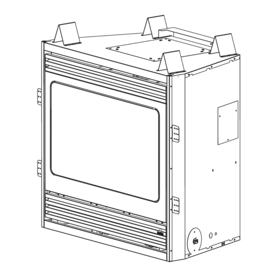
MAX60 (Shown with the FFMAX1 Face)
For Residential Use - Meets all HUD requirements for
manufactured housing installations.
This appliance may be installed as an OEM installation in a manufactured (mobile) home and must be installed in accordance with the manufacturer's
instructions and the Manufactured Home Construction and Safety Standard, Title 24 CFR, Part 3280 or Standard for Installation in Mobile
Homes, CAN/CSA Z240 MH. For assistance during installation contact your local dealer or contact the Heatilator Technical Services Department,
Hearth & Home Technologies Inc., 1915 W. Saunders St., Mt. Pleasant, IA 52641. This appliance may be installed in an aftermarket permanently located,
manufactured (mobile) home, where not prohibited by local codes. This appliance is only for use with the type of gas listed on the rating plate. This
appliance is not convertible for use with other gases, unless a certified conversion kit is used.
Improper installation, adjustment, alteration, service or maintenance can cause injury or property damage. Refer to this
manual. For assistance or additional information, consult a qualified installer, service agency or the gas supplier.
09/04
INSTRUCTIONS
FOR MANUFACTURED (MOBILE) HOMES:
WARNING!
30484 Rev Q
WARNING:
If the information in this manual
is not followed exactly, a fire or explosion may
result causing property damage, personal in-
jury or loss of life.
— Do not store or use gasoline or other flammable
vapors and liquids in the vicinity of this or any
other appliance.
— What to do if you smell gas
• Do not try to light any appliance.
• Do not touch any electrical switch; do not use
any phone in your building.
• Immediately call your gas supplier from a
neighbor's phone. Follow the gas supplier's
instructions.
• If you cannot reach your gas supplier, call the
fire department.
— Installation and service must be performed by a
qualified installer, service agency or the gas
supplier.
CAUTION:
Do not expose the appliance to the elements (such as
rain, etc.).
1
Advertisement
Table of Contents

Related Manuals for Heatilator Maxus MAX60L

Summary of Contents for Heatilator Maxus MAX60L
- Page 1 Manufactured Home Construction and Safety Standard, Title 24 CFR, Part 3280 or Standard for Installation in Mobile Homes, CAN/CSA Z240 MH. For assistance during installation contact your local dealer or contact the Heatilator Technical Services Department, Hearth & Home Technologies Inc., 1915 W. Saunders St., Mt. Pleasant, IA 52641. This appliance may be installed in an aftermarket permanently located, manufactured (mobile) home, where not prohibited by local codes.
-
Page 2: Table Of Contents
MAXUS DIRECT VENT HEATER PLEASE RETAIN THIS MANUAL FOR FUTURE REFERENCE TABLE OF CONTENTS A. Listings and Code Approvals ........................3 B. Appliance Specifications ..........................5 C. Locations and Clearances ........................... 7 D. Framing/Setting the Appliance ........................9 E. Venting ..............................10 F. -
Page 3: Listings And Code Approvals
If any assistance is required during installation please contact your local dealer or contact the Heatilator Technical Services Department, Hearth & Home Technologies Inc., 1915 W. Saunders St., Mt. Pleasant, IA 52641, 1-800-927-6841. - Page 4 MAXUS DIRECT VENT HEATER Rating Plate Located in the Heater (Example only) WARNING! This valve has been preset at the factory. Altering settings may result in fire hazard or bodily injury. 30484 Rev Q 09/04...
-
Page 5: Appliance Specifications
DVP-TV Vertical Termination Cap DVP45 45-deg Elbow DVP90 90-deg Elbow (for Heatilator appliances only) DVP90ST 90-deg Starter Elbow (should be the first 90-deg elbow used) RF6M Roof Flashing (vertical termination for 0/12 to 6/12 pitch) - pack of four RF12M... - Page 6 MAXUS DIRECT VENT HEATER Note: Minimum and maximum clearances must be Tools and building supplies normally required for installation: maintained at all times. Illustrations throughout these instructions reflect typical installations and are for design Wall-finishing purposes only. Actual installation may vary slightly due Pliers materials to individual design preferences.
-
Page 7: Locations And Clearances
MAXUS DIRECT VENT HEATER C. LOCATIONS AND CLEARANCES Appliance Dimensions WARNING! Due to high temperatures, the appliance should be located out of traffic and away from furniture and draperies. 1. Clearances to Combustible Materials Figure 1 illustrates appliance clearances to combustible materials. - Page 8 MAXUS DIRECT VENT HEATER 2. Locations and Space Requirements Figure 2 illustrates different ways the appliance may be located in a room and the space required. This appliance may be installed directly on the floor or raised on a hearth. Adjacent combustible side walls must be located a minimum of 12 in.
-
Page 9: Framing/Setting The Appliance
MAXUS DIRECT VENT HEATER D. FRAMING/SETTING THE APPLIANCE 1. Frame the Appliance Figure 3 shows typical framing and mantel heights of this appliance using combustible materials. All required clearances to combustibles must be adhered to. Figure 3 - Framing CAUTION: CAUTION: Provide adequate clearances around the air Wear gloves and safety glasses... -
Page 10: Venting
MAXUS DIRECT VENT HEATER E. VENTING 1. Remove the Vent Covers and Place the Collars This appliance may be vented off the rear or off the top. Depending on your specific installation, a vent cover will need to be removed from either the top or rear of the appliance and inner and outer collars attached. Looking at the rear or top of your appliance (depending on which venting style you are going to use), there is a square plate, and other parts (see Figure 4) held to the firebox with four screws. - Page 11 MAXUS DIRECT VENT HEATER 3. Rear Venting Attach the collars supplied. See Figure 5. When attaching the 14 in. square plate with an 8 in. hole, there is a heat shield attached. This must be up and face out (away from the appliance). WARNING! The top opening must be When rear venting,...
- Page 12 MAXUS DIRECT VENT HEATER 4. Top Venting 5. Horizontal Termination Use the 5 in. diameter collar assembly (with the Clearances attached gasket) and the four screws removed earlier See Figures 7 and 8 for clearance information. to attach the collar assembly where the last plate was removed.
- Page 13 MAXUS DIRECT VENT HEATER Vent Lengths for Top Venting (for rear venting, see page 14) Various venting configurations are shown in Figures 9-12 from which maximum vent lengths can be determined. Figure 9 Figure 11 Vent Lengths with One Elbow Vent Lengths with Two Elbows (Minimum Vertical) Figure 10...
- Page 14 MAXUS DIRECT VENT HEATER Vent Lengths for Rear Vent No Elbows The maximum horizontal run, with no vertical sections of vent, is 24 in. from the back of the appliance to the base of the cap. See Figure 13. Figure 13 No Elbows A 45 degree Elbow For corner installations with horizontal...
- Page 15 MAXUS DIRECT VENT HEATER Assembling Vent Sections Figures 17-18 show how to install a typical vent system. Use only pipe listed for use with this Attach a straight section, a 45 degree elbow or a appliance. See page 5 for a description of listed 90 degree elbow, depending on your specific components.
- Page 16 MAXUS DIRECT VENT HEATER Secure the shield to the framing as shown in The small leg on the shield should rest on the Figure 19. top of the vent to properly space it from the pipe section (this heat shield is not necessary on top vented appliances).
- Page 17 MAXUS DIRECT VENT HEATER This page intentionally left blank. 09/04 30484 Rev Q...
- Page 18 MAXUS DIRECT VENT HEATER Figure 22 Termination Cap Locations Figure 23 - Alcove Clearances Figure 24 - Electrical Service Clearances Figure 25 - Cap Clearances 30484 Rev Q 09/04...
- Page 19 MAXUS DIRECT VENT HEATER Dimension Descriptions Clearance above the ground, a veranda, porch, deck or balcony - 12 in. (30 cm) minimum. * Clearance to window or door that may be opened – 10,000 BTUs or less, 6 in. (15 cm) minimum; 10,000-50,000 BTUs, 9 in. (23 cm) minimum;...
- Page 20 MAXUS DIRECT VENT HEATER 6. Vertical Termination Top and Rear Vent Clearances See Figure 26 for clearance information. Starter Elbow Figure 26 Vertical Termination Clearances (Top Vent Shown) Figure 28 Vertical Termination Vent Lengths Top Vent Lengths Various venting configurations are shown in Figures 27-28 from which maximum vent runs CAUTION: can be determined.
- Page 21 MAXUS DIRECT VENT HEATER Rear Vent Lengths Firestop Spacer/Vent Installation Attach either a straight section, a 90 degree elbow, Frame an opening and install a firestop spacer or a 45 degree elbow (depending upon your whenever the vent penetrates a ceiling/floor area, specific installation) to the appliance.
- Page 22 MAXUS DIRECT VENT HEATER Chase/Termination Installation Figure 31 and Table 1 specify minimum vent heights for various pitched roofs. These vent heights are necessary for safety and do not ensure draft-free operation. Trees, buildings, adjoining roof lines, adverse conditions, etc. may create a need for a taller vent should down drafting occur.
-
Page 23: Utilities
Input should be reduced 4% for each 1000 ft above sea level. Check with the local gas utility for proper orifice size identification. The correct orifice is available from your Heatilator distributor. For Canada, appliances are certified for elevations from 0-4500 ft. When installing this appliance at an elevation between 0-4500 ft in Canada, the input rating does not need to be reduced. - Page 24 MAXUS DIRECT VENT HEATER WARNING! This valve has been preset at the factory. Altering settings may result in fire hazard or bodily injury. 3. Gas Pressure An inlet pressure tap and an outlet pressure tap are available on the faces of the standing pilot and the electronic ignition gas valves.
- Page 25 MAXUS DIRECT VENT HEATER 5. Wiring Electronic Ignition This electronic ignition appliance requires a 110VAC supply to operate. It is suggested that a switched 110V junction box with two switched outlets be installed to power the optional remote control and/or fan. This heater listed appliance may be connected to a thermostat.
- Page 26 MAXUS DIRECT VENT HEATER Standing Pilot Ignition This standing pilot appliance does not Note: This appliance must be electrically wired and require a 110VAC supply to operate. It is grounded in accordance with local codes or, in the ab- suggested that a 110V junction box be sence of local codes, with National Electric Code ANSI/ installed with a switched outlet for the NFPA 70-latest edition or the Canadian Electric Code...
-
Page 27: Finishing
MAXUS DIRECT VENT HEATER 6. Install the Junction Box Remove the junction box assembly from the valve compartment. If the box is being wired from the OUTSIDE of the appliance: Loosen two screws on the Romex connector, feed the necessary length of wire through the connector and tighten the screws. -
Page 28: Appliance Preparation
MAXUS DIRECT VENT HEATER H. APPLIANCE PREPARATION WARNING - RISK OF CARBON MONOXIDE! Never operate this appliance with the glass removed or not sealed. WARNING - RISK OF CARBON MONOXIDE! Do not hit or strike glass. Do not operate this appliance if the glass is broken or cracked. Replacement of the glass should be done by a licensed or qualified service person. - Page 29 MAXUS DIRECT VENT HEATER 7. Place the Fire Glow If using lava rock, this rail must be installed to keep the lava rock from interfering with the glass gasket or Fire Glow (Fire 98) is a flame colorant material that retainers.
-
Page 30: Determining The Ignition Type
MAXUS DIRECT VENT HEATER I. DETERMINING THE IGNITION TYPE To determine whether your appliance is an electronic ignition or a standing pilot ignition, open the control access panel to examine the wiring system. If your system has a red ignitor button (as shown in Figure 47), you own a standing pilot ignition appliance. - Page 31 MAXUS DIRECT VENT HEATER 2. Standing Pilot Ignition FOR YOUR SAFETY READ BEFORE LIGHTING WARNING! If you do not follow these instructions exactly, a fire or explosion may result causing property damage, personal injury or loss of life. This gas appliance has a manual ignition device that lights the pilot. When lighting the pilot, follow these instructions exactly.
-
Page 32: Seasonal Checklist
MAXUS DIRECT VENT HEATER K. SEASONAL CHECKLIST WARNING! Children and adults should be alerted to the hazards of high surface temperatures and should stay away to avoid burns or clothing ignition. Young children should be carefully supervised when they are in the same room as the appliance. -
Page 33: Start-Up Issues
MAXUS DIRECT VENT HEATER 1. Electronic Ignition Operation 3. Fuel Conversion Instructions Lighting the Appliance During Regular Use Do not burn wood or other material in the Turn the wall switch to “ON”. appliance. Shutdown During Regular Use Natural or propane gas conversions necessary Turn the wall switch to “OFF”. -
Page 34: Maintenance Instructions
MAXUS DIRECT VENT HEATER M. MAINTENANCE INSTRUCTIONS 1. Clean the Burner and Control Compartment Your air shutter is provided in the “CLOSED” position for natural gas and in the “OPEN” position for propane. Keep the burner and control compartment clean by It takes 16 full turns (360 deg) to move the air shutter brushing and vacuuming at least once a year. - Page 35 Vacuum all remaining glass pieces with a shop vac. Do not vacuum if the pieces are hot! Replace the glass only with a Heatilator glass panel assembly ordered through your local distributor. Never use substitute material. Only ceramic glass may be used on this appliance.
-
Page 36: Replacement Parts
MAXUS Service Parts Exploded Parts Diagram Beginning Manufacturing Date: N/A Ending Manufacturing Date: Active 11/03 30484 Rev Q 09/04... - Page 37 MAXUS Service Parts Service Parts List Beginning Manufacturing Date: N/A Ending Manufacturing Date: Active Description of Part MAX 60 MAX60L Qty. R Air Baffle, Rear 31047 31047 Air Deflector 28705 28705 BC12 Thermal Plate 31360 31360 Burner Front Air Rail 30478 30478 Exhaust Collar Assembly...
- Page 38 MAXUS Service Parts Exploded Parts Diagram Beginning Manufacturing Date: N/A Ending Manufacturing Date: Active 11/03 30484 Rev Q 09/04...
- Page 39 MAXUS Service Parts Service Parts List Beginning Manufacturing Date: N/A Ending Manufacturing Date: Active Description of Part MAX 60 MAX60L Qty. R Bulkhead 35403 35403 Bulkhead Service Pack 4001-041 4001-041 Burner Pan Assembly 31476 30461 Connector, Male, Brass - Flex 17069 17069 Flex Gas Line...
-
Page 40: Optional Components
MAXUS DIRECT VENT HEATER O. OPTIONAL COMPONENTS FK160 RC-SMART-HTL BC10 Fan Kit Remote Control Fan Motor Rheostat RC-ELEC-HTL BC11 Remote Control Automatic Variable Blower Control (Electronic Ignition) BC12 RC-BATT-HTL Variable Fan Control with Thermostat Battery-operated Remote Control (Standing Pilot) HEAT-ZONE RCT-MLT-HTL Multi-functional Remote SMART-STAT-HTL... - Page 41 MAXUS DIRECT VENT HEATER This page intentionally left blank. 09/04 30484 Rev Q...
- Page 42 MAXUS DIRECT VENT HEATER This page intentionally left blank. 30484 Rev Q 09/04...
-
Page 43: Index
MAXUS DIRECT VENT HEATER INDEX Air Shutter 34 Gas Codes 3, 24 Rating Plate 4 Gas Line 23 Appliance Clearances 7 Replacement Parts 36, 37, 38, 39 Gas Line Connection 23 Appliance Locations 8 Rock Wool 28 Gas Log Set 28 Roof Pitch 22 Gas Pressure 24 BTUs 24... -
Page 44: Warranty
If the Heatilator Appliance is found to be defective in either material or workmanship within one year of the date of original installation, HHT will provide replacement parts at no charge and pay reasonable labor and freight costs, and is for the period of one year following the date of original installation of the Appliance.
Need help?
Do you have a question about the Maxus MAX60L and is the answer not in the manual?
Questions and answers