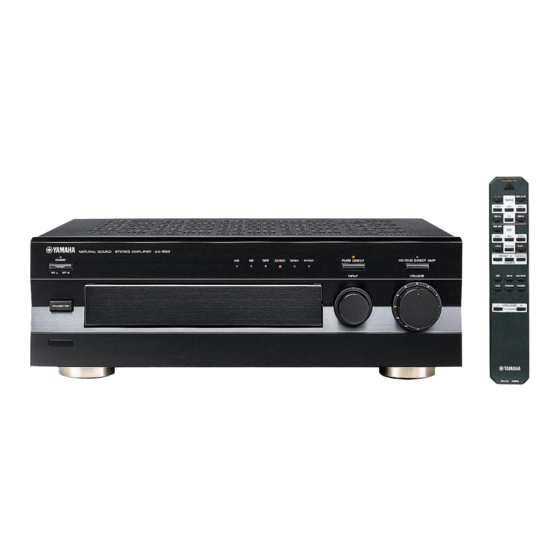
Yamaha AX-596 Service Manual
Hide thumbs
Also See for AX-596:
- Service manual (26 pages) ,
- Owner's manual (19 pages) ,
- Product catalog (44 pages)
Table of Contents
Advertisement
Quick Links
CONTENTS
1 0 0 7 1 7
Downloaded from
www.Manualslib.com
This manual has been provided for the use of authorized YAMAHA Retailers and their service personnel.
It has been assumed that basic service procedures inherent to the industry, and more specifically YAMAHA Products, are already
known and understood by the users, and have therefore not been restated.
WARNING:
Failure to follow appropriate service and safety procedures when servicing this product may result in personal
injury, destruction of expensive components, and failure of the product to perform as specified. For these reasons,
we advise all YAMAHA product owners that any service required should be performed by an authorized
YAMAHA Retailer or the appointed service representative.
IMPORTANT:
The presentation or sale of this manual to any individual or firm does not constitute authorization, certification or
recognition of any applicable technical capabilities, or establish a principle-agent relationship of any form.
The data provided is believed to be accurate and applicable to the unit(s) indicated on the cover. The research, engineering, and
service departments of YAMAHA are continually striving to improve YAMAHA products. Modifications are, therefore, inevitable
and specifications are subject to change without notice or obligation to retrofit. Should any discrepancy appear to exist, please
contact the distributor's Service Division.
WARNING:
Static discharges can destroy expensive components. Discharge any static electricity your body may have
accumulated by grounding yourself to the ground buss in the unit (heavy gauge black wires connect to this buss).
IMPORTANT:
Turn the unit OFF during disassembly and part replacement. Recheck all work before you apply power to the unit.
.......................................................... 1
.......................................... 2
............................................. 2
.............................................................. 3
........................................................... 5
................................... 5
............................................................. 6
manuals search engine
STEREO AMPLIFIER
AX-596
SERVICE MANUAL
IMPORTANT NOTICE
µ
................................................................. 7
........................................................... 18~27
......................................................... 6
.................................... 8~15
........................................ 16~17
........................ 28
AX-596
Advertisement
Table of Contents

Related Manuals for Yamaha AX-596


Summary of Contents for Yamaha AX-596
-
Page 1: Table Of Contents
This manual has been provided for the use of authorized YAMAHA Retailers and their service personnel. It has been assumed that basic service procedures inherent to the industry, and more specifically YAMAHA Products, are already known and understood by the users, and have therefore not been restated. -
Page 2: Specifications
AX-596 SPECIFICATIONS Power Section General Minimum RMS Output Power Power Supply 8Ω, 20Hz to 20kHz, 0.015% THD 100W + 100W U, C models AC120V, 60Hz B, G models AC230V, 50Hz Maximum Output Power (EIAJ) A model AC240V, 50Hz 1kHz, 10% THD... -
Page 3: To Service Personnel
AX-596 TO SERVICE PERSONNEL 1. Critical Components Information Components having special characteristics are marked s and must be replaced with parts having specifications equal to those originally installed. 2. Leakage Current Measurement (For 120V Models Only) When service has been completed, it is imperative to verify that all exposed conductive surfaces are properly insulated from supply circuits. -
Page 4: Rear Panels
AX-596 REAR PANELS U model C model R model A model Downloaded from www.Manualslib.com manuals search engine... - Page 5 AX-596 B model G model T model J model Downloaded from www.Manualslib.com manuals search engine...
-
Page 6: Internal View
AX-596 INTERNAL VIEW 1 MAIN P.C.B. (9) 2 MAIN P.C.B. (2) 3 MAIN P.C.B. (1) 4 MAIN P.C.B. (5) 5 FUNCTION P.C.B. (13) 6 FUNCTION P.C.B. (4) 7 FUNCTION P.C.B. (5) 8 MAIN P.C.B. (10) 9 MAIN P.C.B. (11) 0 FUNCTION P.C.B. (7) A FUNCTION P.C.B. -
Page 7: Adjustments
AX-596 ADJUSTMENTS Confirmation of Idling Current • Right after Power is switched ON, confirm the voltages measured at R111, R135 (L ch) and R112, R136 (R ch) are between 0.4mV to 8.0mV. • If it exceeds 8.0mV, open (cut off) R175 (L ch), R176 (R ch) and reconfirm the voltage. -
Page 8: Μ-Com Data
AX-596 µ-COM DATA IC308 : M34748E8SP Downloaded from www.Manualslib.com manuals search engine... - Page 9 AX-596 PRINTED CIRCUIT BOARD (Foil side) P. C. B. MAIN (1) To/From FUNCTION (1) From FUNCTION (1) SPEAKERS B To MAIN (5) P. C. B. MAIN (7) From FUNCTION (7) From MAIN (2) From MAIN (9) Downloaded from www.Manualslib.com manuals search engine...
- Page 10 AX-596 PRINTED CIRCUIT BOARD (Foil side) P. C. B. MAIN (2) P. C. B. MAIN (5) SPEAKERS A To MAIN (7) P. C. B. MAIN (11) POWER From MAIN (10) From MAIN (1) P. C. B. MAIN (4) P. C. B. MAIN (9) P.
-
Page 11: Printed Circuit Board
AX-596 PRINTED CIRCUIT BOARD (Foil side) P. C. B. FUNCTION (1) INPUT VOLUME PURE DIRECT CD/DVD DIRECT AMP REC OUT To/From FUNCTION (13) LED3 LED4 P. C. B. FUNCTION (3) VRdn LED3 VRup LED4 VRdn VRup P. C. B. FUNCTION (4) - Page 12 AX-596 PRINTED CIRCUIT BOARD (Foil side) To FUNCTION (4) From FUNCTION (9) P. C. B. FUNCTION (5) P. C. B. FUNCTION (7) P. C. B. FUNCTION (8) PHONES SPEAKERS TAPE CD/DVD TUNER PHONO To/From FUNCTION (1) To FUNCTION (10) To MAIN (1) P.
-
Page 13: Schematic Diagram
AX-596 SCHEMATIC DIAGRAM PHONO EQ AMP 12.7 11.8 12.4 13.0 CD/DVD DIRECT AMP & PURE DIRECT OFF To MAIN (1) see page 17 TONE CONTROL AMP 13.4 -12.8 13.7 12.9 13.0 13.8 13.5 -0.6 -0.6 -13.6 -13.0 VOLUME AMP -13.1 -13.6... - Page 14 AX-596 SCHEMATIC DIAGRAM POWER To/From FUNCTION (1) see page 18 POWER SUPPLY 14.1 14.1 14.1 AC82.0 From FUNCTION (7) IMPEDANCE see page 16 SELECTOR 14.7 17.5 17.5 17.5 POWER SUPPLY 17.5 15.3 14.8 17.6 AC69.2 AC82.0 14.6 17.4 17.5 -17.8 52.0(43.6)
-
Page 15: Parts List
AX-596 WARNING PARTS LIST Components having special characteristics are marked s and must be replaced with parts having specifications equal to those originally in- stalled. ELECTRICAL PARTS Carbon resistors (1/6W or 1/4W) are not included in the ELECTRICAL PARTS List. For the parts No. of the carbon resistors, refer to last page. - Page 16 AX-596 Schm Schm Ref. PART NO. Description Rank Ref. PART NO. Description Rank V5761800 P.C.B. MAIN(J) C151 VG289100 C.EL 330uF (UCABJG) 01 V5761900 P.C.B. MAIN(UC) C152 Vi715500 C.MYLAR 1000pF (UCABJG) 01 V5762000 P.C.B. MAIN(RT) C152 VU019500 C.MYLAR 1000pF 100V(RT) 01 V5762100 P.C.B.
- Page 17 AX-596 Schm Schm Ref. PART NO. Description Rank Ref. PART NO. Description Rank Q102 VK432900 TR 2SD1915F S,T R188 VP939700 R.MTL.FLM 4.7Ω Q103 iA097030 2SA970 GR,BL R189 VP939700 R.MTL.FLM 4.7Ω Q104 iA097030 2SA970 GR,BL R190 VP939700 R.MTL.FLM 4.7Ω Q105 iA097030...
- Page 18 AX-596 Schm Schm Ref. PART NO. Description Rank Ref. PART NO. Description Rank C301 VK533900 C.PP 100pF 200V C364 VG290800 C.EL 4.7uF C302 VK533900 C.PP 100pF 200V C365 VJ599000 C.CE.TUBLR 0.047uF 16V C303 VQ645600 C.MYLAR 100pF C366 VJ599100 C.CE.TUBLR 0.1uF C304 VQ645600 C.MYLAR...
- Page 19 AX-596 Schm Schm Ref. PART NO. Description Rank Ref. PART NO. Description Rank C427 VG287200 C.EL 10uF Q301 iC174020 2SC1740S R,S C428 VG287200 C.EL 10uF Q302 iA093320 2SA933S Q,R C429 VG287200 C.EL 10uF Q303 iA093320 2SA933S Q,R C430 VG287200 C.EL...
- Page 20 AX-596 EXPLODED VIEW 2-30 2-13 2-42 (10) 2-30 (11) 2-42 2-16 2-30 6 (1) 2-30 2-1-1 2-14 6 (3) 2-40 200-1 2-43 6 (11) 2-41 2-2-2 2-1-4 2-15 2-10 2-1-2 2-2-1 2-1-3 2-41 2-42 2-1-4 2-40 2-11 2-40 2-2-4 2-2-3...
- Page 21 AX-596 MECHANICAL PARTS Ref. PART NO. Description Remarks Markets Rank V5272700 FRONT PANEL V5272800 FRONT PANEL V5272900 FRONT PANEL V4598400 ESCUTCHON 5x22 V4598800 LENS, 6P V4598900 LENS, 1P VV185700 LENS, FILTER 7x24 2-1-1 V4596500 SUB PANEL 2-1-1 V4596600 SUB PANEL...
- Page 22 AX-596 Ref. PART NO. Description Remarks Markets Rank * s 8 XT052B00 POWER TRANSFORMER * s 8 XT053B00 POWER TRANSFORMER * s 8 XT055B00 POWER TRANSFORMER * s 8 XT056B00 POWER TRANSFORMER * s 8 XY800A00 POWER TRANSFORMER (RT) V2438700 CORD STOPPER...
- Page 23 AX-596 Ref. PART NO. Description Remarks Markets Rank VY732900 FRAME, TR592 VQ368600 PUSH RIVET P3555-B V4597400 PLATE SIDE L V4597500 PLATE SIDE L V4597600 PLATE SIDE L V4597700 PLATE SIDE R V4597800 PLATE SIDE R V4597900 PLATE SIDE R VZ117300 DAMPER, T5...
- Page 24 AX-596 Parts List for Carbon Resistors Value 1/4W Type Part No. 1/6W Type Part No. Value 1/4W Type Part No. 1/6W Type Part No. 1.0 Ω 3100 3100 10 kΩ 7100 7100 HJ35 HF85 HF45 HF45 1.8 Ω 3180 11 kΩ...
-
Page 25: Remote Control Transmitter
AX-596 REMOTE CONTROL TRANSMITTER SCHEMATIC DIAGRAM Downloaded from www.Manualslib.com manuals search engine... - Page 26 AX-596 Downloaded from www.Manualslib.com manuals search engine...
Need help?
Do you have a question about the AX-596 and is the answer not in the manual?
Questions and answers