Table of Contents
Advertisement
Operation, Installation and Service Manual
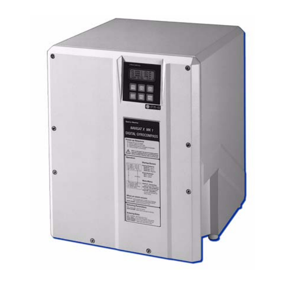
NAVIGAT X MK 1
Digital Gyrocompass Systems
Type 4914-CA, Stock No. 74807 and Type 4914-CC, Stock No. 74811
056343/C, 08 May 2008
Northrop Grumman Sperry Marine B.V. (Representative Office)
Woltmanstr. 19 • D-20097 • Hamburg, Germany
Tel.: +49-40-299 00-0 • Fax: +49-40-299 00-146 • E-mail: service.de@sperry.ngc.com
Advertisement
Table of Contents

Summary of Contents for NORTHROP GRUMMAN NAVIGAT X MK 1
- Page 1 Digital Gyrocompass Systems Type 4914-CA, Stock No. 74807 and Type 4914-CC, Stock No. 74811 056343/C, 08 May 2008 Northrop Grumman Sperry Marine B.V. (Representative Office) Woltmanstr. 19 • D-20097 • Hamburg, Germany Tel.: +49-40-299 00-0 • Fax: +49-40-299 00-146 • E-mail: service.de@sperry.ngc.com...
- Page 2 NAVIGAT X MK 1 © 2008 Northrop Grumman Sperry Marine B.V. This document and the information herein is the intellectual property of Northrop Grumman Sperry Marine B.V. [NGSM BV] and it’s associate companies and may not be copied or repro- duced without the express permission of NGSM BV.
-
Page 3: Safety Instructions
NAVIGAT X MK 1 056343/C Safety Instructions Safety Notice Conventions The following safety notice conventions are followed throughout this manual: A Danger notice contains an operating or main- DANGER tenance procedure, practice, condition, state- ment, etc., which, if not strictly observed, will result in injury or death of personnel. -
Page 4: General Safety Information For The Operator
WARNING After a power-up from cold, the NAVIGAT X MK 1 requires a settling time of three hours before reliable heading data is available. Power up the system at least three hours before leaving harbour. -
Page 5: General Safety Information For Service Personnel
CAUTION The NAVIGAT X MK 1 contains electrostatic sensitive components. Electrostatic discharge may permanently damage components. When servicing the NAVIGAT X MK 1, take precautions to prevent elec- trostatic discharge. Avoid touching any of the electronic circuitry. CAUTION It cannot be guaranteed that parameter settings in the User and Setup menus and the entries made in the Magnetic Compass Calibration table are left intact when the software is exchanged. - Page 6 056343/C NAVIGAT X MK 1 1-iv...
-
Page 7: Table Of Contents
Design and Main Features................ 1-1 Operating Principle ................... 1-2 Example System Configurations ............. 1-3 Standalone Gyrocompass/TMC System ..........1-3 Dual NAVIGAT X MK 1 Gyrocompass/TMC System ........ 1-4 Technical Data.................... 1-5 Chapter 2: Operation Operating Conditions ................2-1 Display and Operating Keys ..............2-2 Control and Display Unit ................ - Page 8 056343/C NAVIGAT X MK 1 Chapter 3: Errors and Alarms Alarm Indication ..................3-1 Audible Alarm Indication ................3-1 Visual Alarm Indication................3-1 Acknowledging Alarms/Muting the Audible Alarm....... 3-2 Alarm Acknowledge .................. 3-2 Alarm Mute ....................3-2 Error messages ..................3-3 Service Info Menu (Service Setup 2) ............
- Page 9 NAVIGAT X MK 1 056343/C Chapter 7: System Configuration Configuration Menu (Service Setup 1)............ 7-1 Setup Access Code..................7-1 Service-Setup 1 – Overview ..............7-2 Service Setup 1 – Parameters ..............7-6 Factory Settings Menu (Technical Pages) ..........7-16 Setup Access Code.................. 7-16 Technical Pages –...
- Page 10 056343/C NAVIGAT X MK 1 viii...
-
Page 11: Chapter 1: Introduction
The HSC-version (stock no. 74811) with a specially selected gyrosphere also complies with IMO resolution A.821(19). The rate of turn output of the NAVIGAT X MK 1 complies with IMO reso- lution A.526(13). The NAVIGAT X MK 1 has been type approved by the German Federal... -
Page 12: Operating Principle
056343/C NAVIGAT X MK 1 1.2 Operating Principle The north-seeking element used in the NAVIGAT X MK 1 system is the gyrosphere, a hermetically sealed unit with a funnel-shaped recess, reaching from the outer skin down to its center. Inside the gyrosphere, two mechanically linked gyroscopes are mounted with their spin axes horizontal in a carrying frame. -
Page 13: Example System Configurations
1.3 Example System Configurations Standalone Gyrocompass/TMC System As a standalone system, the NAVIGAT X MK 1 provides North-speed error corrected true heading as well as rate of turn data. If a fluxgate sensor, type 4863, or an electronic magnetic compass is installed, the NAVIGAT X MK 1 applies magnetic variation and distrib- utes magnetic heading data to external equipment (TMC function). -
Page 14: Dual Navigat X Mk 1 Gyrocompass/Tmc System
The system shown in Figure 1-3 below is the standard configuration for a dual NAVIGAT X MK 1 gyrocompass system. In addition to the two NAVIGAT X MK 1 compasses, this system com- prises the NAVITWIN IV heading management system and the Switch- Over Unit Type 4932. -
Page 15: Technical Data
NAVIGAT X MK 1 056343/C 1.4 Technical Data Accuracies heading: ≤ 0.1° secant latitude lin. mean settle point error ≤ 0.1° secant latitude static error ≤ 0.4° secant latitude dynamic error deviation after 3 min. power interruption < 2° ≤ 0.5°/minute... - Page 16 056343/C NAVIGAT X MK 1 Dimensions and Weight width 404 mm height 520 mm depth 420 mm weight 25 kg approx. Data Inputs ext. gyro heading NMEA 0183 / IEC 61162-1 or PLATH protocol or Lehmkuhl (1200, 2400, 4800 or 9600 Bd.)
- Page 17 NAVIGAT X MK 1 056343/C Data Outputs serial repeater outputs NMEA 0183 (12x TTL) sensor data outputs NMEA 0183 / IEC 61162-1 (4x RS-422; 3 available if AD10 output active) FAST output NMEA 0183 / IEC 61162-1 (1x RS-422) or PLATH protocol...
- Page 18 056343/C NAVIGAT X MK 1 Technical Data...
-
Page 19: Chapter 2: Operation
The supporting fluid in the gyrosphere container will start freezing at temperatures below 0 °C. The NAVIGAT X MK 1 may no longer be operated when the ambient tem- perature at the gyrocompass’ location falls below –10 °C while the com- pass is in operation or when the ambient temperature falls below 0 °C... -
Page 20: Display And Operating Keys
056343/C NAVIGAT X MK 1 2.2 Display and Operating Keys Control and Display Unit Figure 2-1: NAVIGAT X MK 1 control and display unit ÿÿÿÿÿÿÿÿÿÿÿÿÿÿÿÿÿÿÿÿ ÿÿÿÿÿÿÿÿÿÿÿÿÿÿÿÿÿÿÿÿ ÿÿÿÿÿÿÿÿÿÿÿÿÿÿÿÿÿÿÿÿ ÿÿÿÿÿÿÿÿÿÿÿÿÿÿÿÿÿÿÿÿ Display ➀ LCD Display: 4x20 character text display In normal operational mode, shows the available heading sources and the heading diff. -
Page 21: External Control Devices
(apply a 180° offset to the heading data), e.g. for operation in double- ended ferries. • The audible alarm at the NAVIGAT X MK 1 the may be muted from a remote device, e.g. a central alarm panel. External control devices... -
Page 22: Power-Up Sequence
056343/C NAVIGAT X MK 1 2.4 Power-up Sequence The NAVIGAT X MK 1 is not equipped with a power switch. The gyro- compass powers up as soon as supply power is applied. Upon power up, the startup routine is executed:... -
Page 23: Selecting The Active Heading Source
WARNING Make sure that the NAVIGAT X MK 1 has settled before using its heading as the reference for heading control systems, RADAR, ECDIS, etc. A magnetic heading source should be made active only in case of failure of the gyrocompass(es). -
Page 24: Optional Functions
A remotely muted alarm remains in the pending (unacknowledged) state. The alarm message is shown on the display until the alarm is acknowl- edged at the NAVIGAT X MK 1 or the cause of the alarm is eliminated. Reversing the Heading Display (180° offset) To reverse the heading display, e.g. -
Page 25: Operating Menu
F1 DISPLAY DATA F2 MANUAL SETTINGS F3 SETUP MENU The NAVIGAT X MK 1 returns to nor- mal operational mode. Navigating the Menu In the menu mode, the operator may navigate through the menu using the F1, F2, F3, Up/Down, Dim+/Dim- and MENU key functions. -
Page 26: Selecting Parameter Settings
056343/C NAVIGAT X MK 1 Selecting Parameter Settings A number of operational and setup parameters are set by selecting the appropriate option from a list. Flashing up/down arrow symbols to the right of a parameter setting indicate that a selection can be made from a list of options: With the Up/Down keys, select the required MAN.SETTINGS... -
Page 27: Selecting A Display Data Page
NAVIGAT X MK 1 056343/C 2.9 Selecting a Display Data Page The Display Data menu allows the operator to select one out of five pages to permanently display relevant operational data, instead of the normal heading display screen. The selected page is displayed until another page is selected or the Dis- play Data mode is quit. -
Page 28: Manual Settings Menu
In case a NAVITWIN compass monitor / heading management system is installed, the manual settings must be entered at the NAVITWIN. The NAVITWIN will overwrite any manual settings entered locally at the NAVIGAT X MK 1 control and display unit. Manual Settings – Overview Figure 2-2: MAN.SETTINGS GYRO 1... - Page 29 NAVIGAT X MK 1 056343/C Figure 2-3: contd. from previous page Manual Settings (cont.d) MAN.SETTINGS GYRO 1û F1 NORTH SP.ERR.CORR north speed error correction NORTH SP. ERR. CORR F2 SET. NAVIPRINT F3 SETTINGS ROT ü nav. data printer settings SET. NAVIPRINT NAVIPRINT PAP.
-
Page 30: Manual Settings - Parameters
056343/C NAVIGAT X MK 1 Manual Settings – Parameters Speed/Latitude Speed/Lat Mode Selects the speed and position input modes. Speed Mode Selects the speed input mode. Settings: AUTO Speed data is read automatically from the serial data or the 200 pulse/nm input... - Page 31 NAVIGAT X MK 1 056343/C Hdg. Diff. Alarm Sets the manual input values for the speed and latitude. Between Selects the heading sources to monitor. Settings: GY1/GY2 Monitor difference between gyros 1 and 2 GY1/MAG Monitor difference between gyro 1 and magnetic hdg.
- Page 32 056343/C NAVIGAT X MK 1 Set. NAVIPRINT Sets the operating parameters for the NAVIPRINT nav. data printer. NAVIPRINT Turns printing on and off. Settings: Activate output to printer No output to printer Pap. speed Sets the paper feed speed. Settings: 60 mm print at 60 mm/h (1 cm = 10 min.).
- Page 33 NAVIGAT X MK 1 056343/C Settings ROT Sets the rate of turn input parameters. Time constant ROT Sets the damping time constant for the analogue rate of turn output. The larger the time constant, the less short-time fluctuations will be present in the analogue rate of turn output voltage.
-
Page 34: User Setup
056343/C NAVIGAT X MK 1 2.11 User Setup The User Setup menu provides access to settings which the operator may need to alter occasionally. User Setup – Overview Figure 2-4: USER SETUP User Setup F1 DATE/TIME DATE/TIME input date/time F2 SOFTWARE VERSION F3 MAG.C. -
Page 35: User Setup - Parameters
NAVIGAT X MK 1 056343/C User Setup – Parameters Date & Time Sets the date and time input parameters. Mode Selects the date and time input mode. Settings: AUTO Date/time are read automatically from the serial data input The current date and time are entered manually Man. - Page 36 056343/C NAVIGAT X MK 1 2-18 User Setup...
-
Page 37: Chapter 3: Errors And Alarms
NAVIGAT X MK 1 056343/C Chapter 3: Errors and Alarms 3.1 Alarm Indication Audible Alarm Indication Single Beep: Invalid Action A single short beep indicates that the operator attempted to carry out an invalid action. This is the case, e.g. if the operator tries to change the heading reference in an automatic steering mode or to activate a head- ing source from which no valid data is received. -
Page 38: Acknowledging Alarms/Muting The Audible Alarm
When the cause of an alarm is eliminated, the alarm is acknowledged automatically and the alarm status is cleared. The NAVIGAT X MK 1 does not keep a history of past (inactive) alarms. Alarm Mute To mute the audible alarm at the NAVIGAT X MK 1: Press Shift-Reset. -
Page 39: Error Messages
NAVIGAT X MK 1 056343/C 3.3 Error messages The following table lists the error messages which may appear on the display and in the error list when a system alarm is active. Table 3-1: Message on Message in Cause Corrective... - Page 40 056343/C NAVIGAT X MK 1 Message on Message in Cause Corrective Display Error List Action POSITION FAILURE POS. Loss of position Check position ERROR data from ext. data source and source. interface. HEADING HEAD. DIFF The monitored Check heading DIFF . ALARM...
-
Page 41: Service Info Menu (Service Setup 2)
NAVIGAT X MK 1 056343/C 3.4 Service Info Menu (Service Setup 2) The Service Setup 2 provides access to system status information which is used during installation and for troubleshooting errors. Furthermore, an option is provided to reset the system without cycling the power (warm start). -
Page 42: Service Setup 2 - Overview
056343/C NAVIGAT X MK 1 Service Setup 2 – Overview Figure 3-2: SERVICE SETUP 2 Service Setup 2 F1 GYROSPHERE DATA GYROSPHERE DATA gyrosphere operational data F2 OP.TIME COUNTER F3 DATA LIST ü TEMPERATURE: gyrosphere ambient temperature PH. BRIDGE: phase bridge voltage GYRO CURR.: gyrosphere current... -
Page 43: Service Setup 2 - Parameters
NAVIGAT X MK 1 056343/C Service Setup 2 – Parameters Gyrosphere Data Displays the gyrosphere operating data. Displays: Temperature The ambient temperature around the gyrosphere container. Ph. Bridge The follow-up circuit phase bridge voltage. Gyro Curr. The gyrosphere current. Op. Time Counter Displays the gyrosphere operation time counter. - Page 44 056343/C NAVIGAT X MK 1 Service Info Menu (Service Setup 2)
-
Page 45: Chapter 4: Scheduled Maintenance
Use only water and soap or a mild detergent to clean the compass. 4.2 Gyrosphere Maintenance Specifications The gyrosphere is the only component of the NAVIGAT X MK 1 which requires regular maintenance. CAUTION Scheduled maintenance or service work on the gyrosphere is to be car- ried out by authorized service personnel only. -
Page 46: Five-Year Maintenance
056343/C NAVIGAT X MK 1 Five-Year Maintenance To ensure continued trouble-free operation and to minimize the risk of failure, Sperry Marine recommends that every five years, the gyro- sphere and the centring pin are exchanged by authorized service per- sonnel. -
Page 47: Chapter 5: Preventive Maintenance
The supporting fluid in the gyrosphere container will start freezing at temperatures below 0 °C. The NAVIGAT X MK 1 may no longer be operated when the ambient tem- perature at the gyrocompass’ location falls below –10 °C while the com- pass is in operation or when the ambient temperature falls below 0 °C... -
Page 48: Removing The Container From The Compass Housing
056343/C NAVIGAT X MK 1 Removing the container from the compass housing DANGER When the compass is energized, the gyrosphere operating voltage of 100 VAC @ 337 Hz is present on the master PCB, the gyrosphere supply lines, and across the gyrosphere contacts. - Page 49 NAVIGAT X MK 1 056343/C 4. Turn the bellows, until the largest of the three coupling seats in the bayonet collar points towards the front of the housing. The seat is marked by a green dot on the collar. 5. Put both hands around the con-...
-
Page 50: Re-Installing The Container In The Compass Housing
056343/C NAVIGAT X MK 1 Re-installing the container in the compass housing DANGER When the compass is energized, the gyrosphere operating voltage of 100 VAC @ 337 Hz is present on the master PCB, the gyrosphere supply lines and across the gyrosphere contacts. - Page 51 NAVIGAT X MK 1 056343/C 8. Gently lower the container. The coupling tongues engage into their seats in the bayonet and the con- tainer locks in place by its own weight. 9. Plug the gyrosphere supply and pickoff connector into its socket on the gyrosphere container.
-
Page 52: Procedure
056343/C NAVIGAT X MK 1 Power-up function test To verify the correct operation of the re-installed gyrosphere, the settling behaviour of the compass is to be observed. DANGER When the compass is energized, the gyrosphere operating voltage of 100 VAC @ 337 Hz is present on the master PCB, the gyrosphere supply lines and across the gyrosphere contacts. - Page 53 NAVIGAT X MK 1 056343/C 3. During the settling phase, periodically call up the gyrosphere data sub-menu from the Service Setup 2 (code 610), to observe the gyro- sphere current: Directly after power-up, the gyro- GYROSHPERE DATA sphere current should not exceed TEMPERATURE 42 °C...
- Page 54 056343/C NAVIGAT X MK 1 Protecting the Gyrosphere from Low Temperatures...
-
Page 55: Chapter 6: Installation
NAVIGAT X MK 1 056343/C Chapter 6: Installation 6.1 Mechanical Installation The NAVIGAT X MK 1 gyrocompass system comprises the compass housing complete with installed base plate assembly and master PCB, the gyrosphere container, the gyrosphere and the installation and replacement parts kit. -
Page 56: Electrical Installation
The NAVIGAT X MK 1 is delivered prewired for connection to 230VAC. A wire link connects transformer terminal 5 to terminal 6. If the system is required to operate on 115 VAC, wire links must be installed to link terminal 4 to terminal 6 and terminal 5 to terminal 7. -
Page 57: Gyrosphere Installation
NAVIGAT X MK 1 056343/C If installation-specific connection diagrams have been provided for a given system, these supersede any connection information contained in standard connection diagrams. Ship's cables are directly connected to screw-down terminals on the master PCB. Insert the ship's cables through the inlets at the sides of the compass housing. -
Page 58: Initial System Configuration
Man- ual Settings menu. If a magnetic heading source is connected to the NAVIGAT X MK 1, the magnetic compass calibration procedure should be carried out during a sea trial, as described under "Magnetic Compass Calibration" below6.5. - Page 59 NAVIGAT X MK 1 056343/C To finalize the installation: 1. Set the operational parameters the Manual Settings menu to suita- ble values. Wherever possible, automatic data input should be selected in preference of manual input. 2. Enter the current date and time in the User Setup menu.
-
Page 60: Alignment Error Correction
056343/C NAVIGAT X MK 1 6.5 Alignment Error Correction In order to obtain correct heading data, the existing alignment error (i.e. the angular difference between the compass orientation and the vessel's fore-and-aft axis) must be determined and the required correction applied. -
Page 61: Magnetic Compass Calibration
If magnetic heading is received from an already calibrated source, such as a NAVITWIN, NAVIPILOT or a self-calibrating electronic compass, cal- ibration at the NAVIGAT X MK 1 is not required and must be disabled. CAUTION The magnetic heading calibration corrects deviations due to the com- bined effects of the magnetic environment, the particular sensor being used and the receiving circuitry on the master PCB. - Page 62 F3 MAGN.C. 270.9° DIFF G1/G2 5°ü magnetic heading values shown on the NAVIGAT X MK 1 display. At every full 10° of steering magnetic compass heading (0°, 10°, ... , 350°), note the display value. Mag. HDG 6.
- Page 63 NAVIGAT X MK 1 056343/C Storing the magnetic heading calibration table 1. Call up the User Setup and go to the ’Magn Cal Tab’ sub-menu. Press Shift-F1. (’enter values’) The calibration table entry sub-menu is shown. 2. To enter the previously determined correction values:...
- Page 64 056343/C NAVIGAT X MK 1 6-10 Alignment Error Correction...
-
Page 65: Chapter 7: System Configuration
7.1 Configuration Menu (Service Setup 1) The Service Setup 1 provides access to the system parameters which configure the NAVIGAT X MK 1 according to the requirements of the installation at hand. The Service Setup 1 also provides a test mode to check the proper func- tion of the serial and 6 step/°... -
Page 66: Service-Setup 1 - Overview
056343/C NAVIGAT X MK 1 Service-Setup 1 – Overview Figure 7-1: SERVICE SETUP 1 Service Setup 1 F1 INTERFACE I/O INTERFACE I/O interface configuration F2 ANALOG ROT OUTP. F3 FEEDBACK SIGNALü GYRO INPUT PLATH LEHMK. 1200 LEHMK. 2400 LEHMK. 4800 LEHMK. - Page 67 NAVIGAT X MK 1 056343/C Figure 7-2: contd. from previous page Service Setup 1 (contd.) SERVICE SETUP 1 F1 INTERFACE I/O F2 ANALOG ROT OUTP. ANALOG ROT OUTP. settings analog ROT output F3 FEEDBACK SIGNALü sc. factor: 0.1 – 999.9 mV/°/min zero offset: -999 –...
- Page 68 056343/C NAVIGAT X MK 1 Figure 7-3: contd. from previous page Service Setup 1 (contd.) SERVICE SETUP 1 û F1 EXT. STATUS IN EXT. STATUS IN ext. status input function F2 NAME OF GYRO F3 TEST MODE ü STATUS IN STAT.
- Page 69 NAVIGAT X MK 1 056343/C Figure 7-4: contd. from previous page Service Setup 1 (contd.) SERVICE SETUP 1 û F1 K1 MUTE/HDG-DIFF K1 MUTE/HDG-DIFF alarm relay K1 functionality F2 SPEED FILTER HDG-DIFF MUTE SPEED FILTER speed filter settings for error correction t.
-
Page 70: Service Setup 1 - Parameters
056343/C NAVIGAT X MK 1 Service Setup 1 – Parameters Interface I/O Configures the in- and output interfaces. Gyro Input Selects the interface protocol for the ext. Gyro input. Settings: PLATH The input reads the PLATH binary data protocol LEHMK. 1200 The input is reads the Lehmkuhl (Scandinavian Microsys- tems) protocol at 1200 Bd. - Page 71 NAVIGAT X MK 1 056343/C Mag Hdg. Inp. Configures the magnetic heading input. Settings: SIN COS The input reads analogue voltages from a Sperry Marine fluxgate sensor type 4863 at the analogue fluxgate interface NMEA-HDM The input reads the NMEA $--HDM sentence at the NMEA magn.
- Page 72 056343/C NAVIGAT X MK 1 Sens. D. M. Outp. Selects the output sentence format for magnetic heading at the sensor data outputs Settings: NMEA-HCHDM Magnetic heading is sent using the NMEA $--HDM sentence with talker ID “HC” NMEA-HCHDT Magnetic heading is sent using the NMEA $--HDT sentence with talker ID “HC”...
- Page 73 NAVIGAT X MK 1 056343/C NMEA SuperFAST Configures the SuperFAST serial data output. Settings: 4800 Baud The output transmits all available data in NMEA format at 4800 Bd. (standard according to IEC 61162-1) 9600 Baud The output transmits all available data in NMEA format at 9600 Bd.
- Page 74 056343/C NAVIGAT X MK 1 Analog ROT Outp. Configures the analogue rate of turn output. Sc. Factor Sets the scaling for the output. Value: 0.1 – 999.9 mV/°/min. Zero Offset Sets the zero-point offset for the output. Value: -999 – 999 mV Feedback Signal Configures the rudder angle feedback inputs.
- Page 75 NAVIGAT X MK 1 056343/C System Type Configures the system type and the heading selector device. System Sets the system configuration Settings: Single gyrocompass system: the control and display unit shows own gyro heading only; the heading source selection and heading difference alarm functions are not available.
- Page 76 056343/C NAVIGAT X MK 1 Align Err. Corr. Sets the alignment error correction value Settings: -179.9 – +180.0 ° Shaft Cor. Angle Sets the shaft encoder correction value Settings: -179.9 – +180.0 ° Ext. Status In Configures the external status signal input port...
- Page 77 NAVIGAT X MK 1 056343/C Name Of Gyro Sets the compass ID. Settings: Standalone single gyro or main gyro in multiple gyrocom- pass system. Backup gyro in a dual or triple gyrocompass system. Backup gyro in a triple gyrocompass system.
- Page 78 056343/C NAVIGAT X MK 1 Gen. Alarm Setup Selects in which cases the “General Alarm” relay is actuated. Settings: On all alarms The relay is actuated whenever an alarm condition exists. On fatal alarms The relay is actuated only in case of fatal alarms. A fatal alarm exists when the gyrocompass can no longer provide its own heading data.
- Page 79 When this option is selected, relay K1 is actuated whenever an alarm is acknowledged or muted locally at the NAVIGAT X MK 1. In multicompass systems which also require a heading dif- ference alarm output, a separate compass monitoring device, such as the NAVITWIN IV, must provide the heading difference alarm.
-
Page 80: Factory Settings Menu (Technical
056343/C NAVIGAT X MK 1 7.2 Factory Settings Menu (Technical Pages) The Technical Pages provide access to a number of factory-set parame- ters which need not normally be altered. However, should the system software need to be exchanged, these settings will be lost and must be re-entered manually. -
Page 81: Technical Pages- Parameters
NAVIGAT X MK 1 056343/C Technical Pages– Parameters Software Version Displays detailed hard- and software version information. Settings: Hardware The revision code of the master PCB. SW Ver. The creation date of the system software. Masterboard The version code of the system software. - Page 82 056343/C NAVIGAT X MK 1 7-18 Factory Settings Menu (Technical Pages)
-
Page 83: Chapter 8: Troubleshooting
Chapter 8: Troubleshooting 8.1 Troubleshooting Instructions The NAVIGAT X Mk 1 is a complex electronic system. In case of malfunc- tion, it would neither be practical nor economical to carry out trouble- shooting and servicing in the field down to the level of individual circuit components. -
Page 84: Location Of Parts On The Master Pcb
056343/C NAVIGAT X MK 1 8.2 Location of Parts on the Master PCB Figure 8-1 below shows the locations of exchangeable components, connectors, trimpots and diagnostic LED indicators on the master PCB. Figure 8-1: TB 7 TB 6 TB 5... -
Page 85: Exchangeable Components
NAVIGAT X MK 1 056343/C Exchangeable Components Table 8-1: Part Function Stock No. Exchangeable compo- IC 5 quad RS-422 output driver IC; 046485-0000-000 nents on the master drives Sensor Data TB 7.1/7.2 and 7.3/7.4, Compass Monitor, Display units IC 6 quad RS-422 output driver IC;... -
Page 86: Test Resistor / Trimpots
Diagnostic LEDs As an aid in troubleshooting, a number of diagnostic LED indicators are provided on the NAVIGAT X MK 1 PCB. These indicate the presence of supply voltages, activities on the serial data I/O lines and the current states of the status I/O ports. - Page 87 NAVIGAT X MK 1 056343/C Colour Indication CR 30 green activity on Tx line, Sens. Data or AD10 clock, TB 7.13/7.14 CR 31 green activity on Tx line, SuperFast or AD10 data, TB 7.11/7.12 CR 32 overload 24VDC out to Switch-Over Unit, TB 3.22...
- Page 88 056343/C NAVIGAT X MK 1 Colour Indication CR 105 overload 24VDC out to repeater 10 CR 106 overload 24VDC out to repeater 11 CR 110 green activity on Rx line, ext. Gyro, TB 4.1/4.2 CR 111 green activity on Rx line, Magnetic Heading, TB 4.17/4.18...
-
Page 89: Chapter 9: Corrective Maintenance
NAVIGAT X MK 1 056343/C Chapter 9: Corrective Maintenance The NAVIGAT X MK 1 is generally not field-serviceable on the compo- nent level. In case of malfunction, complete sub-assemblies must be exchanged and the defective sub-assemblies returned to Sperry Marine. -
Page 90: Replacing Socketed Ics
056343/C NAVIGAT X MK 1 Exchanging the flash-memory IC Note The flash-memory IC is a 32-pin PLCC chip. A suitable extractor tool is required to remove the IC from its socket. Verify that a new flash-memory IC, stock no. 26562, containing software 4914-1090-00 with the required revision identifier and release date has been obtained. -
Page 91: Appendix
4914-0125-03 Table Note After installation of the NAVIGAT X MK 1, please return a filled-out copy of the Setup Table to Sperry Marine for inclusion in the ship’s file. When permanent changes are made to the system configuration, please return an updated copy of the Setup Table to Sperry Marine. - Page 92 056343/C NAVIGAT X MK 1...
- Page 93 Time Const. ROT: Max. Value ROT: Time Constant: Max. Value: °/min. User Setup Date and Time Mode AUTO Mag. Comp. Cal. Table Northrop Grumman Sperry Marine B.V. (Representative Office) Woltmanstr. 19, D-20097 Hamburg, Germany Tel.: +49-40-299 00-0, Fax: +49-40-299 00-298, E-mail: service.de@sperry.ngc.com...
- Page 95 Date / Signature: Note After installation of the NAVIGAT X MK 1, please return a filled-out copy of the Setup Table to Sperry Marine for inclusion in the ship’s file. When permanent changes are made to the system configuration, please return an updated copy of the Setup Table to Sperry Marine.
- Page 97 Correction values are specific to the master PCB installed. When exchanging a master PCB, read out the correction values and update this setup table to reflect the new values. Northrop Grumman Sperry Marine B.V. (Representative Office) Woltmanstr. 19, D-20097 Hamburg, Germany Tel.: +49-40-299 00-0, Fax: +49-40-299 00-298, E-mail: service.de@sperry.ngc.com...
- Page 99 80.0 260.0 90.0 270.0 100.0 280.0 110.0 290.0 120.0 300.0 130.0 310.0 140.0 320.0 150.0 330.0 160.0 340.0 170.0 350.0 Northrop Grumman Sperry Marine B.V. (Representative Office) Woltmanstr. 19, D-20097 Hamburg, Germany Tel.: +49-40-299 00-0, Fax: +49-40-299 00-298, E-mail: service.de@sperry.ngc.com...
Need help?
Do you have a question about the NAVIGAT X MK 1 and is the answer not in the manual?
Questions and answers