Table of Contents
Advertisement
Advertisement
Table of Contents

Summary of Contents for B&B Molders Nautilus P1
- Page 2 INSTALLATION INSTRUCTIONS Items Included in System Polar White Part #’s 301-032-00002 301-032-00006 301-032-00011 Black Part #’s 301-032-00003 301-032-00005 Atmospheric Vacuum Spin Weld ABS Tank Spray Head Breaker/Check Valve Spray Head Part #571 Sprayer Part #571 VAC CHK Part #631 Label Part #103-002-00014 58471 Fir Road, Mishawaka, IN 46544 Phone: (574) 259-7838 Fax: (574) 259-7939...
- Page 3 INSTALLATION INSTRUCTIONS Improper installation, operation or servicing this product will result in equipment damage & personal injury. This product should be installed & serviced by qualified technical personnel who have an in-depth knowledge of the construction process and potential hazards of this type of system.
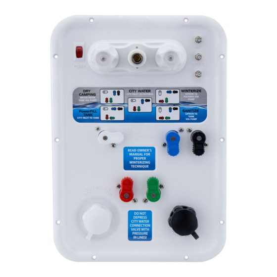
- Page 4 INSTALLATION INSTRUCTIONS IMPORTANT!! NEVER push check valve on "CITY WATER" connection with pressure in line. This WILL cause irreparable damage to the check valve function. 58471 Fir Road, Mishawaka, IN 46544 Phone: (574) 259-7838 Fax: (574) 259-7939 Page 2 of 15 www.bandbmolders.com...
- Page 5 INSTALLATION INSTRUCTIONS INSTALLATION INSTRUCTIONS Nautilus P1 Handle Position and Valve Routing Information WHITE HANDLE : Receives water from water inlet on front of panel Sideways – water goes into blue handle diverter Down – water goes to pump inlet BLUE HANDLE : Receives water from white handle valve/water inlet on front of panel Sideways –...
- Page 6 INSTALLATION INSTRUCTIONS PLUMBING HARNESSES There are five different plumbing harnesses that are necessary on the Nautilus P1 Panel. FRESH WATER TANK "IN" HARNESS: HOT FIXTURES HARNESS The (Fresh Water Tank In) line has two panel The (Hot Fixtures) line has two connections...
- Page 7 INSTALLATION INSTRUCTIONS PLUMBING HARNESSES WATER INLET HARNESS WITH WATER FILTER WITHOUT WATER FILTER If unit has a water filter, connect "WATER If unit does not have a water filter, run plumbing INLET" at bottom of panel to (Filter In) and line from "WATER INLET"...
- Page 8 INSTALLATION INSTRUCTIONS PLUMBING HARNESSES COLD WATER SUPPLY HARNESS PUMP INLET HARNESS The (Cold Water Supply) line has four connections Line to (Pump Inlet) has two connections marked marked with a on back side of Nautilus panel: with a on back side of Nautilus panel: "TO "COLD"...
- Page 9 INSTALLATION INSTRUCTIONS PLUMBING HARNESSES - OTHER Line from (Fresh Water Tank Out) has one Line from (Pump Out) has one connection on connection on back of Nautilus panel: "IN FROM back of Nautilus panel: "PRESSURE FROM TANK." PUMP." Line to (Hot Water Heater In) has one connection on back of Nautilus panel: "TO H2O HEATER."...
- Page 10 INSTALLATION INSTRUCTIONS 2. Connect plumbing harness (Cold Water 1. Cut a 10" x 15" opening in substrate material Supply) to back of Nautilus panel at four & feed appropriate connections through opening. locations marked with a . Screw plumbing swivel fittings onto diverter valve ends in the following order: "FIXTURES (PUMP),"...
- Page 11 INSTALLATION INSTRUCTIONS 3. Connect plumbing harness (Pump Inlet) 4. Connect plumbing harness (Fresh to back of Nautilus panel at two locations Water Tank) to back of Nautilus panel at two marked with a . Screw plumbing swivel locations marked with a .
- Page 12 INSTALLATION INSTRUCTIONS 5A. UNITS WITH WATER 5B. UNITS WITHOUT WATER FILTER FILTER Connect plumbing line running from (Filter In) to Connect plumbing harness (Water Inlet) "WATER INLET" located at bottom of Nautilus to back of Nautilus panel at two locations panel.
- Page 13 INSTALLATION INSTRUCTIONS 7. Connect plumbing harness (Hot Fixtures) 6. Connect plumbing line running from (Hot to back of Nautilus panel at two locations Water Heater In) to diverter valve end marked with a . Screw plumbing swivel labeled fittings onto diverter valve ends in the following "TO H2O HEATER"...
- Page 14 INSTALLATION INSTRUCTIONS 8. Connect plumbing line running from (Pump 9. Connect plumbing line from (Fresh Water Out) to diverter valve end labeled "PRESSURE Tank FROM PUMP" on back of Nautilus panel. Out) to diverter valve end labeled "IN FROM TANK" on back of Nautilus panel. Connections shall be hand tight + ¼...
- Page 15 INSTALLATION INSTRUCTIONS 11. Connect necessary coaxial cables to 10. Connect plumbing line running from bottom to appropriate connection identified on top left of listed Vac/Check to inlet labeled of panel and hand tighten. "TANK FLUSH." 12. Connect power service to terminals on back of pump switch located on top right of panel as illustrated below.
- Page 16 INSTALLATION INSTRUCTIONS 13. Secure panel to substrate material using (10) #8 self-tapping pan headed screws. 58471 Fir Road, Mishawaka, IN 46544 Phone: (574) 259-7838 Fax: (574) 259-7939 Page 13 of 15 www.bandbmolders.com...
- Page 17 INSTALLATION INSTRUCTIONS INSTALLATION INSTRUCTIONS TANK FLUSHER SYSTEM INSTALLATION 1. Vac/Check connected to tank flush inlet should be 2. Connect plumbing line running from discharge located a minimum of 6" above flood rim of highest side of Vac/Check down to sprayer installed fixture connected to waste holding tank.
- Page 18 INSTALLATION INSTRUCTIONS INSTALLATION INSTRUCTIONS SPRAYER INSTALLATION Rotational Molded Tank – Spin Weld Application With a router that spins at over 20,000 rpm, 1. Drill a 1" hole on end or side of waste holding tank, NOT TO EXCEED 2" BELOW TOP insert white/clear sprayer device into special tool/chuck making sure it is well seated.
Need help?
Do you have a question about the Nautilus P1 and is the answer not in the manual?
Questions and answers