Advertisement
Quick Links
Advertisement

Summary of Contents for UIrobot UIM2901-5A
- Page 1 r Ma UIM290 01-5A ACH3 3 Break kout B Board ...
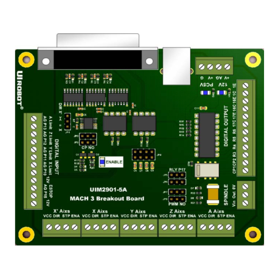
- Page 2 UIM2901-5A MACH3 Breakout Board UIM2901-5A MACH3 breakout board Features General DB25 interface between PC and user device Fully buffered opto-isolated I/O (Input / Output) Ports Motor Driving Output Support 5 stepping motor simultaneously, X’, X, Y, Z, A ...
-
Page 3: Typical Wiring Schematic
UIM240xx Stepper Motor Driver, it may be used for other stepper motor drivers. User control devices (such as PC) connect to the UIM2901-5A through a male to male DB25 cable. The logic side (user device side) electronics are powered by either a USB cable or a standalone 5VDC power supply. - Page 4 PCB. 2.1 DB25 Connector Schematic UIM2901-5A uses a male to male DB25 cable to communicate with the MACH3 software. The definition of each PIN is provided in the Figure 2-1. Al input signals are opto-isolated and buffered.
- Page 5 UIM2901-5A 2.2 Motor and Charge Pump Control Circuit By shorting the left two pins (near the mark of JP2/JP3) of both JP2 and JP3, MACH3’s Charge Pump feature can be enabled. Charge Pump action will disable all UIM240 Stepper Drivers and the Charge Pump relay, which can cause stepper motors and spindle to stop.
- Page 6 UIM2901-5A MACH3 Breakout Board 2.3 Digital Input and Output Circuit By shorting the left two pins (near the legend of JP5/JP6) of both JP5 and JP6, the onboard relay can be enabled and controlled through DB25 pin 17. Pin 16 can be used as open-collector control output. Please note that, P16C links to the opto- isolator’s collector pin and the P16E links to the emitter pin.
- Page 7 UIM2901-5A 2.4 Spindle Control Circuit By shorting the left two pins (near the legend of JP7/JP8) of both JP7 and JP8, a PWM wave will be generated to provide a voltage used to control the spindle speed. Figure 2-4 Spindle Control Circuit ...
- Page 8 UIM2901-5A MACH3 Breakout Board Ports and Pins Configuration of MACH3 3.1 Port Setup Figure 3-1 Port Setup 3.2 Motor Driving Step and Direction Configuration Figure 3-2 Motor Driving Step and Direction Configuration Page | 9 ...
- Page 9 UIM2901-5A 3.3 Limit Switch Configuration Figure 3-3 Limit Switch Configuration (I) Figure 3-4 Limit Switch Configuration (II) Page | 10 ...
- Page 10 UIM2901-5A MACH3 Breakout Board Page | 11 ...
- Page 11 UIM2901-5A 3.6 Charge Pump Feature Configuration Figure 3-7 Digital Input and Output Circuit Page | 12 ...
-
Page 12: Appendix A Dimensions
UIM2901-5A MACH3 Breakout Board Appendix A Dimensions 4x 3.6 Units: mm Page | 13 ...
Need help?
Do you have a question about the UIM2901-5A and is the answer not in the manual?
Questions and answers