Table of Contents
Advertisement
Quick Links
Advertisement
Table of Contents

Subscribe to Our Youtube Channel
Summary of Contents for Western Scale m2000D
- Page 1 2000D technical manual high speed 3 channel digital indicator Manual Release for V1.03D of software We are continuously improving the manual and will send out updated versions as soon as the manual has been finalized. More examples and features will be added. JUNE 2002...
- Page 2 Information in this technical manual is subject to change without notice due to correction or enhancement. The information described in this manual is the property of Western Scale. No part of this manual may be reproduced or transmitted in any form, without the express written permission of Western Scale.
- Page 3 2000D technical manual IGITAL CALE LLOCATION UIDE INTRODUCTION NTRODUCTION TO DLC SCALE ALLOCATION ………. GENERAL INSTALLATION ENERAL INSTALLATION GUIDE ……………………….. SECTION SCALE INSTALLATIONS ECTIONAL SCALE INSTALLATONS……………………... HOPPER SCALE INSTALLATIONS OPPER SCALE INSTALLATIONS ……………………….. GENERAL DLC COMMANDS ENERAL ALLOCATION RELATED COMMANDS……... GENERAL CABLE CONNECTIONS ENERAL CABLE CONNECTION GUIDE…………………...
-
Page 4: Table Of Contents
2000D technical manual ONTENTS M2000D SYSTEM INTRODUCTION.......................1 GENERAL OVERVIEW..........................1 MAIN FEATURES ..........................1 M2000D SYSTEM SPECIFICATIONS....................2 M2000D DIGITAL SYSTEM DIAGRAM....................3 TYPES OF SCALE SYSTEMS SUPPORTED..................4 DLC CHANNEL ALLOCATION......................4 SCALE SETUP USER INTERFACE......................6 GENERAL INSTALLATION GUIDE ......................9 INTRODUCTION AND OVERVIEW......................9 POWER SUPPLY CONNECTION......................9 LOAD CELL CONNECTION ........................10... - Page 5 Reload Scale Allocation (field replacements): calibration command ..........34 Scale Status/Diagnostics Information: non-calibration command..........36 DLC Slave Line Status: non-calibration command ..............37 GENERAL CABLE CONNECTION GUIDE ..................39 M2000D INDICATOR CONNECTIONS ....................39 DLC CONNECTIONS ...........................40 SINGLE DLC SLAVE CONNECTION....................41 DUAL DLC SLAVE CONNECTION – TYPE 1..................42 DUAL DLC SLAVE CONNECTION –...
-
Page 6: M2000D System Introduction
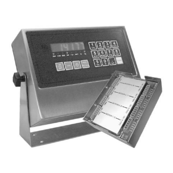
RFI /EMI interference, as required by industrial installations. INTRODUCTION The M2000D system consists of an indicator and one or two DLC slave units. The DLC slaves consist of 8 load cells per DLC. The digital system has no AD converters inside the indicator itself. -
Page 7: M2000D System Specifications
Temperature Range -10C to +40C ENCLOSURES M2000D-DT 6x9.75x2.5 Stainless Steel Desktop (External Power Supply) M2000D-NSB Swivel Stand 7.25x10x3 Stainless Steel NEMA with mounting for one option board M2000DNSS Light Weight 8x10x4 Stainless Steel NEMA with option board mounting plan M2000D-NSS-... -
Page 8: M2000D Digital System Diagram
SCALE 3 Sectional (4 sections) Hopper(4 corners) Hopper (4 corners) INTRODUCTION DLC (P)RIMARY DLC (S)ECONDARY Œ • Ž • Œ • Ž • SCALE 2 SCALE 3 SCALE 1 SECTIONAL SCALE HOPPER SCALE Figure 1: A M2000D Scale Configuration Page 3... -
Page 9: Types Of Scale Systems Supported
The system stores information in the DC slaves as part of a calibration. The other type of scale targeted by the M2000D is the sectional scale as implemented in vehicle scales. A sectional scale consists of 2 or more sections, of which each section consists of two paired load cell channels. - Page 10 2000D technical manual The following restrictions apply to allocating cells for hopper or sectional scales: Hopper Scales Hopper scale corners can be grouped on a single DLC, they cannot be spread across two DLC terminal boxes. Hopper scales can be grouped from any of the cells on a particular DLC slave terminal box.
-
Page 11: Scale Setup User Interface
The indicator is calibrated using the numeric keypad. There are no potentiometers or switches to set. The M2000D consists, like its analog counterpart, of 3 scale channels. To enter calibration mode, type in the scale channel number 19, 29 or 39. - Page 12 2000D technical manual SECTIONAL SCALES SECTIONAL SCALE - This scale allocation is a 4 Channel scale consisting of 4 sections starting on the Primary DLC – Press the [TARE] key to start scrolling through the sections This is the Combination of the section 1 (in this case section 1 of 4 ) –...
- Page 13 2000D technical manual HOPPER SCALES HOPPER SCALE - This scale allocation is a 4 Channel Hopper scale consisting of 4 corners on the Primary DLC corner 1 goes to cell 1 on the Primary DLC terminal box – Press the [TARE ] key to move to the next corner corner 2 goes to cell 2 on the Primary DLC terminal box box –...
-
Page 14: General Installation Guide
Constant voltage transformer for typical industrial installations UPS protection for highly unstable power sources In cases where the M2000D unit might be installed in a vehicle or truck, it is important to provide for power conditioning between the vehicle’s power plant and the indicator. Please consult with your factory representative for more detail. -
Page 15: Load Cell Connection
The cable should provide a separate foil shield for each pair plus a drain wire to be connected to the M2000D shield terminal. Do not connect the shield on the other end of the cable to anything. The recommended cable to be used is type 22 AWG (0.32 sq. -
Page 16: System Grounding
The following information deals with grounding as it relates to lightning and electrostatic discharges to earth ground. The M2000D provides for surge protection, however in order for surge conditions to be diverted properly, a good earth ground path should be in place. - Page 17 2000D technical manual (Intentionally Left Blank) Page 12...
-
Page 18: Sectional Scale Installation Guide
2000D technical manual ECTIONAL CALE NSTALLATION UIDE Sectional scale installations do allow sections across multiple DLC slaves. The following set of instructions is a general guideline on how to allocate and calibrate sectional scales: 1. Install load cell cables to DLC slave units starting from the lowest cell number on the primary slave as labeled on the DLC boxes. -
Page 19: Assign A Sectional Scale: Calibration Command
If the allocation was unsuccessful and other scales do exist that need to stay active, use Commands 501, 502 or 503 to clear only the current scale allocation information. Keep in mind that the M2000D indicator has 3 scales. The following examples illustrate how to interpret the assignment information displayed on the LED display while in calibration mode for a sectional scale. -
Page 20: Sectional Example (1)
2000D technical manual ECTIONAL XAMPLE Once the 4-section scale is allocated, the allocation information pertaining to each section of the sectional scale can be viewed by pressing the [TARE] key to scroll through all the sections and related corners. At any time we can look at the raw counts of a corner or section using the [ON/OFF] key. -
Page 21: Sectional Example (2)
We have two 8 channel DLC slaves for a total of 16 cells We have both Primary and Secondary DLC units connected to the M2000D We require a sectional scale with 6 sections ( total of 12 load cells) - Page 22 2000D technical manual Once we have allocated the sectional scale using command 521, we can use the [TARE] key in calibration mode to scroll through all the sections and related corners and use the [ON/OFF] key to observe the raw counts as required. The table below outlines and explains the status information as we scroll through the sections and corners using the [TARE] key.
- Page 23 2000D technical manual (Intentionally Left Blank) Page 18...
-
Page 24: Hopper Scale Installation Guide
2000D technical manual OPPER CALE NSTALLATION UIDE The following set of instructions is a general guideline on how to allocate and calibrate a hopper scale with no more than 4 load cells per hopper scaled. 1. Install load cell cables to DLC slave unit starting from cell 1 as labeled on the DLC slave. The first corner is always assigned to the cell with the lowest number. -
Page 25: 520 Assign A Hopper Scale: Calibration Command
For example - if a 4-corner hopper scale is required, 4 will be entered. A corner equates to a single cell on the DLC terminal box. The M2000D has 3 scales, to enter calibration mode for any one, use commands 19, 29 or 39. -
Page 26: Hopper Example (1)
2000D technical manual OPPER XAMPLE Once the 4-corner hopper scale is allocated (in calibration mode), the allocation information pertaining to each corner of the hopper scale can be viewed as follows by pressing the [TARE] key while in calibration mode: DLC (P) RIMARY DLC (S) -
Page 27: Hopper Example (2)
We have both Primary and Secondary DLC units connected to the indicator We require 3 hopper scales of 4 corners each The M2000D supports 3 scale channels. We must allocate a single hopper scale per scale channel. First we enter calibration mode for scale 1 by executing command 19, and after entering a password we allocate the first hopper scale using calibration command 520. - Page 28 2000D technical manual The following information can be viewed by entering calibration mode for each of the 3 scales respectively, and using the [TARE] key to scroll through the status information. The hopper scale allocation information for scale 1 on the primary DLC slave would look as follows: HOPPER SCALE 1 - The allocation information indicates that we are...
- Page 29 2000D technical manual (Intentionally Left Blank) Page 24...
-
Page 30: General Allocation Related Commands
GENERAL DLC COMMANDS This command will reset and invalidate the current calibrated scale. The M2000D has 3 scales, to enter calibration mode for any one, use commands 19, 29 or 39. All information will be erased. This command is typically used for a new installation to clear any existing scale allocations to scale 1. -
Page 31: 525 Dlc Load Cell Masking: Calibration Command
2000D technical manual DLC Load Cell Masking: calibration command The purpose of this command is to disable/enable cell channels to be allocated to a scale. This is an advanced feature, for normal scale allocations using commands 520/521 this command would not be necessary. This command is of use where a cell inside a DLC box is not operational or for a custom setup as required. -
Page 32: 530 Reset Corner Field Adjustment Entries: Calibration Command
2000D technical manual Reset Corner Field adjustment entries: calibration command Field adjustment entries are the corner span corrections applied to corners during calibration, these entries would be cleared for new scale installations. Normally command 530 is performed directly after a scale was allocated using commands 520 or 521. This command only affects the selected scale under calibration. -
Page 33: 531 Corner / Section Manual Span Adjustment: Calibration Command
2000D technical manual Corner / Section Manual Span Adjustment: calibration command This command allows the field personnel to adjust for small linearity discrepancies on a corner or section basis for a hopper or sectional scales. This command will act on the currently selected corner or section as outlined in the status display. -
Page 34: Auto Corner Span Adjustment: Calibration Command
2000D technical manual Auto Corner Span Adjustment: calibration command This command allows the field personnel to adjust for small linearity discrepancies on a corner or section basis for a hopper or sectional scales. This command serves the same purpose as command 531 but instead of adjusting weight in a manual way, we simply type in the weight and the system will automatically span the selected corner/section to the target weight. -
Page 35: 551 Dlc Communications Error Counter: Calibration Command
2000D technical manual DLC communications Error Counter: Calibration command This command is accessible from within or outside calibration mode. This command displays the number of aborted packets on the DLC communications line in real time. If this error count seems to increase abnormally high over a short period of time, it may indicate a noisy communications path or a general communications hardware failure. -
Page 36: Dlc Software Upgrade Download: Calibration Command
This command prepares the indicator for a software upgrade to one of the remote DLC slave units. The software is downloaded via the M2000D indicator to one of the DLC slave units using the M2000 download software. For a DLC slave to be upgraded, it must be registered with the system –... -
Page 37: Dlc Set Ad Range For Active Corner: Calibration Command
2000D technical manual DLC Set AD Range For Active Corner: calibration command This command is similar to calibration command 11 but has some distinctions. Command 558 will change the currently displayed corner/section or scale as a whole, depending on which corner the user scrolled to in calibration mode. Use the [TARE] key to scroll to the corner in question while in calibration mode –... -
Page 38: Restore System Setup From Dlc Slave: Calibration Command
2000D technical manual Restore System Setup From DLC slave: calibration command This command is a calibration command. It will restore a previous backup from any one of the two DLC slaves to the master indicator. This command goes hand in hand with calibration command 591 –... -
Page 39: 591 Backup System Setup To A Dlc Slave: Calibration Command
It is important to note that the backup will be generated from the last saved calibration and action table information as stored in the M2000D indicator. The user should first exit calibration mode to make sure that the information is saved to backup memory. - Page 40 2000D technical manual Query Active DLC Cells on Slaves: calibration command This command is a calibration command. This command provides a means of first obtaining the current active cells per DLC slave, and secondly providing the option of changing the number of active AD converters per slave. If the user does not know the number of active cells per slave, the user may simply count the number of installed load cell connectors on the DLC slave.
-
Page 41: 600 Scale Status/Diagnostics Information: Non-Calibration Command
2000D technical manual Scale Status/Diagnostics Information: non-calibration command This command displays the status information pertaining to the currently selected scale. This is a non-calibration command executed outside of calibration mode. First select the scale for which status information is desired from, by using 1, 2 or 3 followed by [PRINT/SELECT]. -
Page 42: Dlc Slave Line Status: Non-Calibration Command
2000D technical manual DLC Slave Line Status: non-calibration command This command can be executed in or outside of calibration mode. This command will indicate to the user how many slaves were found to be online. The results can be interpreted as follows: 0 –... - Page 43 2000D technical manual (Intentionally Left Blank) Page 38...
-
Page 44: General Cable Connection Guide
ENERAL ABLE ONNECTION UIDE M2000D I NDICATOR ONNECTIONS The diagram below is a general outline of the connectors as seen on the back of the circuit board for the M2000D indicator: SMARTWIRE COM2 COM1 3.3V Li Œ•Ž•• Œ•Ž•• Œ•Ž•• BATTERY •... -
Page 45: Dlc Connections
2000D technical manual DLC C ONNECTIONS The diagram below is a general outline of the connectors as seen on the remote DLC terminal boxes: LINK •‚ƒ„… DIGITAL LINK • Œ • • Ž Ž • • Œ • • Œ •... -
Page 46: Single Dlc Slave Connection
2000D technical manual DLC S INGLE LAVE ONNECTION The diagram below demonstrates a typical wiring diagram of load cells to the slave DLC and the DLC slave to the M2000D indicator: DLC SLAVE CORNER2 CORNER1 - EXC - EXC +EXC... -
Page 47: Dual Dlc Slave Connection - Type 1
The diagram below demonstrates a wiring diagram for instances where the two DLC slaves are grouped close to one another but far from the indicator. Please pay attention to the current loop cable configuration when connecting two DLC slaves: DLC SLAVE DLC SLAVE M2000D INDICATOR CTL- CTL+ SHLD Page 42... -
Page 48: Dual Dlc Slave Connection - Type 2
The diagram below demonstrates an alternative wiring diagram for instances where the two DLC slaves are far removed from each other. Please pay attention to the current loop cable configuration when connecting two DLC slaves: DLC SLAVE M2000D INDICATOR SHLD GENERAL CABLE CONNECTIONS... -
Page 49: General Diagnostics
2000D technical manual ENERAL IAGNOSTICS DLC S TATUS NDICATORS The following information describes the use of the 3 status LEDs located on the DLC slave boards as a means of making a meaningful diagnosis of the state of the DLC communications link. - Page 50 2000D technical manual РINK LED LED STATE INTERPRETATION REMEDY ΠPermanently Indicates that network communications If the LINK LED does not light up at all, a link is valid. communications error exist. Check DLC communications cabling. Consult the section on general wiring diagrams for proper connection of communications lines.
- Page 51 2000D technical manual – LED STATE INTERPRETATION REMEDY Œ Permanently Indicates that slave in question is If the TX led does not light up at all, diagnosis responding to commands send by the might be one of the following: indicator and is valid - normal •...
-
Page 52: Error Messages
2000D technical manual Error Messages 1 Invalid parameter number for calibration mode 2 Graduation size invalid 3 Decimal Position Invalid 4 Flag values must be 1 for ‘ON’ and 0 for ‘OFF’ 5 Push to Zero Window must be 0-99 6 Zero tracking must be 1-99 or 100, 200, 300. - Page 53 2000D technical manual 46 * 47 Invalid Filter value 48 Invalid Filter Fast step value 49 Invalid Fast step Sensitivity 50 Invalid Fast step on/off 51 Invalid Tare Function Parameter 0-4 52 Invalid input for AD voltage range 90 Calibration checksum failed 100 SRAM failure 110 RTC RAM failure 112 Clock Reset...
- Page 54 2000D technical manual DLC communications related errors 160 DLC slaves not detected communications failure 161 Scale 1 allocation action table does not verify with slave entries 162 Scale 2 allocation action table does not verify with slave entries 163 Scale 3 allocation action table does not verify with slave entries 165 Slave assigned to a scale but not detected by system 170 Scale 1 allocation action table does not verify with slave entries 171 Scale 2 allocation action table does not verify with slave entries...
Need help?
Do you have a question about the m2000D and is the answer not in the manual?
Questions and answers