
Subscribe to Our Youtube Channel
Summary of Contents for Reflex Marine FROG-3
- Page 1 FROG-3 User Manual Original Instructions For FROG Models: FS-01 (320) Standard FS-01 (340) Arctic FS-01 (370) Tropical Rev 19 | Issued 14-05-12...
-
Page 2: Purpose Of Manual
Purpose of Manual This manual contains general instructions for the operation and maintenance of the FROG-3. Safe and proper use of the FROG-3 is the responsibility of the user after having taken due regard of the information provided in this document. -
Page 3: Document Revision & Control
A list of all revisions and amendments must be included in each controlled copy of this User Manual. Upon revision of the FROG-3 User Manual, the manual will be distributed to the list of document holders indicated below. The control, revision and distribution of this manual will be the responsibility of the Reflex Marine Ltd Lead Engineer –... - Page 4 The parts listings have been removed from the User Manual. Parts regarding Frog listings will in future be available online (or directly from Reflex Marine) 3 operation , where the parts list for the serial number of each Frog can be matched maintenance.
- Page 5 User Manual FROG-3 Link to Index Section 5.12.4: Torque setting for buoyancy fixings added. Section 6.3: Inspection frequency table has been updated to include an ultra-high usage category Section 6.4: The support drawings detailed in the guidance notes have been updated to the new part numbers.
-
Page 6: Distribution List
User Manual FROG-3 Link to Index Distribution List Controlled/uncontrolled copies of this manual are issued to the following: Reflex Marine Ltd Ref. Status Issued To Date Issued Format Master Controlled RML Truro 14 May 2012 Electronic J Cryan RML 1... -
Page 7: Table Of Contents
Table of Contents ............................ 7 INTRODUCTION ..........................10 Scope ............................. 10 Introduction .......................... 10 Safety ............................ 11 Note: Competent Person ........................11 SPECIFICATION FROG-3 ......................... 12 Specification Summary......................12 Design ............................ 13 Certification and Documentation ..................14 OPERATING PARAMETERS ......................15 Introduction .......................... 15 Operating Parameters - Sea State .................. - Page 8 Personal Flotation Devices (PFD’s) ................28 5.11.2 Immersion Suits ......................29 5.12 Stretcher Mode ........................30 5.12.1 Converting FROG-3 to Stretcher Mode (Figure 7) ............30 5.12.2 Stretcher Mode Conversion Procedure ................ 30 5.12.3 Positioning the Stretcher ....................32 5.12.4 3-Seat Mode Conversion Procedure ................
- Page 9 Definition According to Criticality ..................70 11.3 Fastener Specifications ......................70 11.4 Certification ........................... 70 12 APPENDIX D – FROG-3 MARKINGS ....................71 12.1 Essential Marking Requirements ..................71 12.2 Decal - Vinyl Stickers - Located on Outside of Buoyancy Units..........72 12.3...
-
Page 10: Introduction
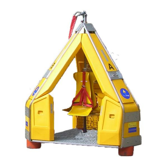
The outer framework protects passengers from impacts and contains the buoyant elements which ensure the FROG-3 floats and is self-righting in water. At its base are keel weights which assist in rapid self-righting. The outer shell lands on three tripod feet that provide shock absorption and ensure that the FROG-3 is stable on uneven surfaces or when landing on a heaving vessel. -
Page 11: Safety
Competent Persons (see note below) experienced in use of the equipment and the local conditions. It is imperative for the safe operation of the FROG-3 that each unit is periodically inspected and tested in accordance with the procedures and schedules set out within this document. -
Page 12: Specification Frog-3
User Manual FROG-3 Link to Index 2 SPECIFICATION FROG-3 2.1 Specification Summary Model No. FS-01 (320) Standard, FS-01 (340) Artic , FS-01 (370) Tropical Payload The Safe Working Load (SWL) of the Frog 3 is the total load of passengers and luggage. SWL = 330 Kg(727 lbs). -
Page 13: Design
User Manual FROG-3 Link to Index Suspension Springs 1 x 8,612 N @ 0.32 m Dampers None 2.2 Design Verification EC Type Examination. ABS Design and Manufacturing Assessment Design review by independent certifying authority Bureau Veritas. Manufactured to ISO 9001:2008. -
Page 14: Certification And Documentation
User Manual FROG-3 2.3 Certification and Documentation Each new build of the FROG-3 is supplied with a set of certification and documentation as specified below. Certification Pack (includes the EC Declaration of Conformity.* following) Manufacturers Certificate of Conformance. Manufacturers BS EN ISO 9001:2008 Certificate. -
Page 15: Operating Parameters
The recommended limits in this section are based on the use of the standard FROG-3 sling length of 30 ft. (9 m). For the use of shorter slings an additional risk assessment combined with dry runs should be performed to establish safe operational routines and weather conditions. -
Page 16: Operating Parameters - Sea State
However, with a qualified Crane Operator, it is considered unlikely that the FROG-3 will be landed at full hook speed on a deck rising at full speed. -
Page 17: Site Specific Frog Transfer Operating Parameters
Visibility Crane Operator should have a clear view of the pickup and set down areas. Vessel Motion / FROG-3 Pitch 10⁰, Roll 10⁰. (FROG-3 stable up to 35⁰ for a load of 1-3 Passengers in Stability static test). Vessel Station-Keeping Able to maintain position within a 5 m (15 ft) radius. -
Page 18: Transfer Planning
User Manual FROG-3 Link to Index 4 TRANSFER PLANNING The key to safe operations is the familiarisation and participation of all the involved crew in the careful planning of the operation. The Operating Parameters detailed within this document are generic, therefore safe operating conditions must be determined by onsite supervision with due regard to site specific equipment, vessels and conditions, taking account of any local conditions and equipment. -
Page 19: Operational Planning
User Manual FROG-3 Link to Index 4.4 Operational Planning An overall plan must be in place for the proposed personnel transfer operation which details all of the relevant information: Installation name. Vessel name. iii. Number of personnel to be transferred - vessel to installation. -
Page 20: Emergency Transfers
User Manual FROG-3 Link to Index 4.8 Emergency Transfers If a transfer must be carried out in poor conditions in an emergency then (where time permits) a ‘trial run’ must be performed without passengers to assess operating conditions and limits. -
Page 21: Operating Procedure
Remain seated until given “All Clear” by the Supervisor. Passengers Exit capsule and move away towards safe area. Note - If risk of vessel losing position or crane line snatch (e.g. vessel to vessel transfers) the FROG-3 must be disconnected for passenger exit and entry. Rev 19... -
Page 22: Crane Operator Guidance
Note: The operating parameters in Section 3.2 are defined for a FROG-3 with a sling length of 30 ft / 9 m. For transfers using a shorter sling an additional risk assessment combined with dry runs should be performed to establish safe operation routines and weather conditions. -
Page 23: Use Of Tag Lines
Tag lines should be attached to the floor grating and 30 x 30 brace at the edge of the doorway (see below). Reflex Marine Ltd suggest one or two 3 m lines are practicable for handling the FROG, however length of line used is at the discretion of the deck crew. -
Page 24: Luggage Storage
FROG-3 5.7 Luggage Storage The FROG-3 is supplied with three luggage storage nets that are located in the corners of the FROG-3 against the lower buoyancy blocks. These provide a pocket in which luggage can be stored (see photo). All luggage items should be stored in the corners so that they do not constitute a tripping hazard for passengers exiting the FROG-3. -
Page 25: Seatbelt Operation
User Manual FROG-3 Link to Index 5.8 Seatbelt Operation Take the lap fastener clip and feed through eye. Fold over the clip and the safety belt is secure. Reverse operation for quick release. Fig 4: Fastening the Belt Next pull the LOWER straps first, then the UPPER straps to make a tight fit. -
Page 26: Rider Instructions
Keep hands and feet inside the FROG-3. Hold the grab handles to keep the body stabilised. iii. Keep feet inside the FROG-3 at all times. Do not hook legs underneath the suspended seats. Fig 6: Position of Body 5.10 Emergency Stop Procedure In the event of an emergency situation the Deck Supervisor / Banksman will give the Crane Operator the emergency stop signal. -
Page 27: Personal Protective Equipment (Ppe)
User Manual FROG-3 Link to Index 5.11 Personal Protective Equipment (PPE) Whilst making the transfer, all personnel must be equipped with appropriate Personal Protective Equipment. Each location and transfer activity will demand a range of differing levels of PPE and RML recommend that PPE requirements are evaluated in recognition of the particular activity and environmental risks that exist at each location. -
Page 28: Personal Flotation Devices (Pfd's)
Link to Index 5.11.1 Personal Flotation Devices (PFD’s) Reflex Marine Ltd has evaluated the 5 most common types of PFD’s used in the offshore and marine sector and has the following comments about their suitability for use with the FROG. -
Page 29: Immersion Suits
1 set for down lift transfers (ready and donned). 1 set for in-transit for next uplift transfers. Total PFD requirement for FROG-3 = 3 x 3 + 1 = 10 PFD’s. iii. Deck crew should ensure that when passengers are exiting the FROG, the passengers move clear of the landing area to the designated safe area before removing PFD’s. -
Page 30: Stretcher Mode
User Manual FROG-3 Link to Index 5.12 Stretcher Mode 5.12.1 Converting FROG-3 to Stretcher Mode (Figure 7) It is recommended that the procedure be conducted by two or three persons. This is to ease handling of the lower buoyancy blocks which weigh approximately 20 kg. - Page 31 User Manual FROG-3 Link to Index Figure 8: Buoyancy Reconfiguration Diagram Refer to Figure 9: Stretcher Fitting Diagram. vii. Remove the lower fixing bolts (2 x M10 Dome Cap) from seat facing door B - C. viii. Loosen the upper fixing bolt (1 x M10 Dome Cap) and loosen the nut from seat facing door B - C.
-
Page 32: Positioning The Stretcher
User Manual FROG-3 Link to Index Figure 9: Stretcher Fitting Diagram 5.12.3 Positioning the Stretcher Complete the ‘Converting to Stretcher Mode’ procedure. Ensure the stretcher casualty is securely strapped into the stretcher. iii. Using three persons to lift the stretcher (two either side at shoulders, one at feet), move stretcher head first through door B - C (door opening with stretcher frame) Note: Observe safe manual handling practice when lifting the stretcher. -
Page 33: Stretcher (Optional) Accessory
User Manual FROG-3 5.12.5 Stretcher (Optional) Accessory Reflex Marine Ltd provides an optional basket type stretcher as illustrated in Figure 10. Figure 10: Basket Type Stretcher (optional) Specifications: Length 2180 mm Width 1 610 mm Depth 190 mm Weight 10 kg... -
Page 34: Periodic Inspection, Testing And Maintenance
Link to Index 6 PERIODIC INSPECTION, TESTING AND MAINTENANCE 6.1 Introduction It is imperative for the safe operation of the FROG-3 that each unit is periodically inspected and tested in accordance with procedures and schedules set out in this section. 6.2 Definitions... -
Page 35: Frequency Of Inspection, Test And Maintenance
/ modifications reports must be sent to the party controlling the use of the FROG- Reflex Marine Ltd is pleased to provide direct technical advice to support users with any inspection, testing, repair or refurbishment query. It is always helpful if customers provide detailed photos and reports along with their query to support@reflexmarine.com. - Page 36 2500 to 5000 3 months 6 months 3 months 6 months 3 years Test Replacement *This may be extended subject to a ‘condition & service assessment’ carried out by RML (Reflex Marine Ltd) or an ASC (Accredited Service Centre). Rev 19 Page36...
-
Page 37: Pre-Operational Visual Check
A suitable means of safely accessing the top and the bottom parts of the FROG-3 is required. When using a step ladder or ladder it must be securely fixed to prevent slippage whilst accessing the top of the FROG. The FROG-3 keel assembly can be visually checked from ground level using a torch. - Page 38 User Manual FROG-3 Link to Index Pre-Operational Visual Check – 10 POINT Check Check Description Reference Main Lift-Eye Plug Check main lifting eye is fully engaged (the machined shoulder should rest on top of the threaded main lifting column). Main Lift-Eye Plug M16 Bolts...
-
Page 39: Visual Inspection
The following checklist is suggested as a suitable list of required inspection items and a suitable format for recording key inspection data. A ‘WORD and EXCEL’ copy of this inspection checklist is included on the distributed CD’s and is also available on the Reflex Marine Ltd website at www.reflexmarine.com/support. - Page 40 Main Seat Spring Check The Frog-3 Spring can be susceptible to yield over time. The Frog-3 spring is deemed fit for purpose until it yields beyond 5% in length. This can be verified by measuring the free length of the spring or measuring the deflection of the seat base in-situ.
- Page 41 Documentation / Report - Complete a report as recommended in the RML inspection template. Reflex Marine Ltd offer to keep an archive copy of your inspection records against the unit number. You can submit your completed checklists and photographs on www.reflexmarine.com/support.
-
Page 42: Examination
The following checklist is suggested as a suitable list of required Examination items and a suitable format for recording key Examination data. A ‘WORD and EXCEL’ copy of this Examination checklist is included on the distributed CD’s and is also available on the Reflex Marine Ltd website at www.reflexmarine.com/support. - Page 43 Both threads should then be coated with either Rocol Anti- Seize Stainless or Swagelok Blue Goop thread lubricant. Do not go underneath an active lift. Replace appropriate parts according to the usage of the FROG-3 (see Table 3 in Section 6.3) or on the recommendation of a Competent Person / Inspector.
- Page 44 If the spring shows excessive corrosion or has started to compress then it should be changed out. The Frog-3 Spring can be susceptible to yield over time. The Frog-3 spring is deemed fit for purpose until it yields beyond 5% in length. This can be verified by measuring the free length of the spring or measuring the deflection of the seat base in-situ.
- Page 45 Documentation / Report - Complete a report as recommended in the RML inspection template. Reflex Marine Ltd offer to keep an archive copy of your inspection records against the unit number. You can submit your completed checklists and photographs on www.reflexmarine.com/support.
-
Page 46: Post Load Test Visual Inspection
FROG-3 is required. When using a step ladder or ladder it should be securely fixed to prevent slippage whilst accessing the top of the FROG. The FROG-3 can be laid on its side on protective matting, or the use of a secure inspection frame assembly to safely access the underside of the FROG-3 is recommended. - Page 47 Check the spring condition and test the operation of the spring. 1. In-situ check The Frog-3 Sliding Sleeve Cross Bolt Runner should rest against the slotted Sliding Sleeve, with a pre-compression force of approximately 60kg. If a space exists between the slot edge and the Cross Bolt Runner greater then 13mm, the Spring should be replaced.
- Page 48 Documentation / Report - Complete a report as recommended in the RML inspection template. Reflex Marine Ltd offer to keep an archive copy of your inspection records against the unit number. You can submit your completed checklists and photographs on www.reflexmarine.com/support.
-
Page 49: Proof Load Testing
Good lighting. A suitable means of safely accessing the top and the bottom parts of the FROG-3 is required. When using a step ladder or ladder it must be securely fixed to prevent slippage whilst accessing the top of the FROG. -
Page 50: Load Test Procedure
Lift the unit and hold static for 5 minutes. minutes. Note: The Tare Weight of the FROG-3 is approximately 485 kg but may vary slightly. Each FROG-3 must be weighed prior to load test. 6.8.2 Inspection Data Plate An inspection data plate will be issued and attached by the test house, which should show: Tare Weight (kg). -
Page 51: Sling Replacement And Management
12 months. 6.9.2 Sling Set Management The wire rope sling set supplied for use with the FROG-3 capsule is a critical component. Good management of sling sets is essential for ensuring safe personnel transfers. -
Page 52: Spares Kits And Replacement Parts
Reflex Marine Ltd can supply critical and non-critical replacement parts as individual items or as appropriate kits. Prior to ordering any replacement parts or part kits, establish the FROG-3 Serial Number which is stamped on the Inspection Data Plate. The Number is typically FS-XXX where XXX represents a three digit number. -
Page 53: Spares Kits
1 x M10 Nyloc Nut 1 x M3 Split Pin 1 x Tamperproof seal Arctic FROGs Refer to FROG-3 (340) unit serial 1 x Main Lift-Eye Plug (M40 version) (340) number for correct kit number 2 x M16 Main Lift-Eye Securing Bolts... - Page 54 And either For Type 1 (older) Keel Assemblies 1 x M48 Coarse (or Fine) Thread Nut (M40 version) (subject to FROG-3 serial number) 1 x Roll Pin 2 x M10 X 60 mm Hex Bolts 2 x M10 Nyloc Nuts...
- Page 55 For Type 1 (older) Keel Assemblies F-RPK-03-340 1 x M48 Coarse (or Fine) Thread Nut (M40 (for unit serial numbers FS-213 version) (subject to FROG-3 serial number) onwards) 1 x Roll Pin 2 x M10 X 60 mm Hex Bolts...
- Page 56 User Manual FROG-3 Link to Index LIFTING SLING ASSEMBLY PARTS KITS Kit Name Kit Number Contents Standard FROG 220-30-A 1 x 30 ft (9 m) Sling Set Assembly c/w 3 (320) – 30ft 2 x Shackles Lifting Assembly 1 x Sling Cover (red)
-
Page 57: All Other Replacement Parts
Usage envelope. Customs processing time. Cost of logistics for small parts. Reflex Marine Ltd would be pleased to offer the recommended minimum stock items for critical and replacement parts for your operation, please contact support@reflexmarine.com. 6.11 Unit Replacement Recommendation The FROG design is strong and robust and is able to be refurbished to full working capacity. FROGs work in a very wide range of operating conditions and environments. -
Page 58: Unit Identification
Every FROG-3 built is assigned a build serial number. These serial numbers are allocated sequentially in the order in which FROG-3 units are built. Serial numbers start from FS-001, and continue in numerical sequence. The serial number for each FROG-3 will be stamped on a plate, which is attached to each unit. -
Page 59: Handling, Shipping And Storage
8.2.2 Crane When lifting the FROG-3 with short chain or strop, a temporary shackle should be fixed to the back- up eyebolt. Care must be taken not to damage the FROG-3 lifting sling set. The shackle should not be fitted through the thimble of the sling eye. -
Page 60: Preparation For Road Transport
FROG-3 weatherproof protective cover or other heavy duty tarpaulin material. 8.2.6 Containerisation The FROG-3 will not fit in a standard or high-cube container. If the FROG-3 is transported on flat rack it must be secured. Recommended securing points are the radial / peripheral floor braces. To protect it from excess loading, the main lifting eye must not be used as securing point. -
Page 61: Storage
User Manual FROG-3 8.2.7 Storage The FROG-3 has been designed to cope with the harsh conditions on an offshore installation or vessel; however it is important to protect the unit as much as possible from any hazardous elements and UV degradation. -
Page 62: Appendix A - Transfer Log
User Manual FROG-3 Link to Index 9 APPENDIX A – TRANSFER LOG MARINE PERSONNEL TRANSFER LOG Date From (vessel name) Transfer Time To (vessel name) Unit Type Crane (port / starboard etc) Wind Speed Sea State Wind Direction Visibility Transfer Classification... -
Page 63: Appendix B - Drawings
User Manual FROG-3 Link to Index 10 APPENDIX B – DRAWINGS Drawing No Revision Description 320 (Sheet 1 & 2) FROG 3 General Assembly 320-01 (Sheet 4) FROG 3 General Assembly (Medivac Configuration) 320-03 (Sheet 1) FROG 3 Central Column Assembly... - Page 64 User Manual FROG-3 Link to Index Rev 19 Page64...
- Page 65 User Manual FROG-3 Rev 19 Page65...
- Page 66 User Manual FROG-3 Rev 19 Page66...
- Page 67 User Manual FROG-3 Rev 19 Page67...
- Page 68 User Manual FROG-3 Rev 19 Page68...
- Page 69 User Manual FROG-3 Rev 19 Page69...
-
Page 70: Appendix C - Parts And Material Specifications
Critical components are those in which, if failure were to occur, there would be a high risk to the safety of the passengers in the FROG-3. The critical components are all connected to the Main Support Tube, which is the prime structural component in the design. -
Page 71: Appendix D - Frog-3 Markings
User Manual FROG-3 Link to Index 12 APPENDIX D – FROG-3 MARKINGS 12.1 Essential Marking Requirements The FROG-3 should be indelibly marked with the following information: CE Mark. Description of Equipment. iii. Model. Serial Number. Manufacturer’s Address. Year of Construction. -
Page 72: Decal - Vinyl Stickers - Located On Outside Of Buoyancy Units
2 off Rectangle Reflex Marine Ltd URL “www.reflexmarine.com” - 250 x 100. 1 off Rectangle Reflex Marine Ltd Tel No “+44 (0)1872 321155” - 250 x 100. Buoyancy columns numbered "A, B, C" Arial bold 150 mm height, black on upper buoyancy. -
Page 73: Decal - Operating Instructions - Located On Seat Back
User Manual FROG-3 Positioned as follows: Column A Column B Column C Operating Instructions 2 x A4 page Seat Change Out Plan Stretcher Fitting Guide SWL Rating Safety Notice – “Keep Feet Inside Frog” 12.5 Decal - Operating Instructions - Located on Seat Back 3 off sticker "ENSURE THAT BELTS ARE PROPERLY ADJUSTED AND TIGHTENED BEFORE LIFT-OFF"... -
Page 74: Frog-3 Column Marking Plan
User Manual FROG-3 12.6 FROG-3 Column Marking Plan Rev 19 Page74... -
Page 75: Appendix E - Accessories
FROG-3 Link to Index 13 APPENDIX E – ACCESSORIES Reflex Marine Ltd provides a range of flexible accessories to optimise the use of the FROG-3. Skid Trolley Specially designed trolley for ease of movement of the FROG-3 to areas that are undercover or otherwise outside the normal reach of the crane and for ease of storage. -
Page 76: Appendix F - Independent Certification
User Manual FROG-3 Link to Index 14 APPENDIX F – INDEPENDENT CERTIFICATION 14.1 EC Type examination certificate (from unit number FS 412 onwards) Rev 19 Page76... -
Page 77: Abs Product Design Assessment Certificate (From Unit Number Fs 412 Onwards)
User Manual FROG-3 14.2 ABS Product Design Assessment Certificate (from unit number FS 412 onwards) Rev 19 Page77...
Need help?
Do you have a question about the FROG-3 and is the answer not in the manual?
Questions and answers