
Related Manuals for National Flooring Equipent 8000 series

Summary of Contents for National Flooring Equipent 8000 series
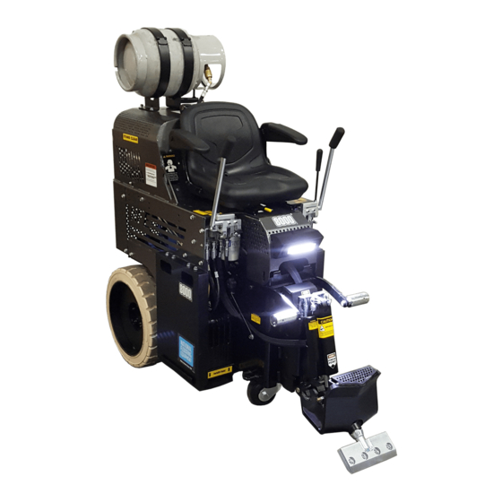
- Page 1 8000 PROPANE RIDE-ON SCRAPER SERVICE MANUAL Read Manual Before Servicing Machine 402974 Rev E...
-
Page 3: Table Of Contents
Table of Contents Table of Contents ........................................3 Specifications ......................................... 4 Safety ............................................5 General Rules For Safe Operation ................................5 Ride-On Scraper Safety Guidelines................................6 Hydraulic Safety......................................7 Maintenance Schedule ......................................8 Troubleshooting Guide ......................................9 Maintenance .......................................... 10 Dual Slide Plate Removal ................................... -
Page 4: Specifications
Specifications Fire Extinguisher Propane Fuel Tank Hydraulic Steering Cylinder Adjustment Headlight Adjustable Foot Pegs Adjustable Slide Plate Non-Marking Tires Fork Lift Cups Quick-Change Swivel Cutting Head Product Specifications Weight (Machine Width Length Height Weight Speed Only) 30” 63” 61” 2,842 lb Up to 200 ft/min. -
Page 5: Safety
Safety GENERAL RULES FOR SAFE OPERATION Before use, anyone operating or performing maintenance on this equipment must read and understand this manual, as well as any labels pack- aged with or attached to the machine and its components. Read the manual carefully to learn equipment applications and limitations, as well as potential hazards associated with this type of equipment. -
Page 6: Ride-On Scraper Safety Guidelines
Safety Safety RIDE-ON SCRAPER SAFETY GUIDELINES Before use, anyone operating this equipment must read and understand these safety instructions. Battery Scraping Do not drive machine along hills or uneven surfaces. Remove personal metal items when working with batteries. The weight of the machine may become distributed differently if on A battery can produce a short circuit current sufficient enough to an uneven surface. -
Page 7: Hydraulic Safety
Safety HYDRAULIC SAFETY Maintaining a Safe Work Environment Establishing a safe work environment in and around your hydraulic equipment is extremely important. The easiest and most effective way to avoid problems is to make sure associates understand their equipment, know how to operate the machines safely, and recognize the dangers if handled carelessly. -
Page 8: Maintenance Schedule
Maintenance Schedule Interval After After initial initial First 8 1000 Maintenance to be performed Daily 50 hrs Check all machine components for build ● up; clean if necessary Inspect all safety devices (e-stop, backup ● beeper, seat switch) Inspects for leaks (hoses and fittings) ●... -
Page 9: Troubleshooting Guide
Troubleshooting Guide Problem Cause Solution The scraper does not work when the pump is Severe blockage in wheel drive motor hoses. Check for blockage and replace hose(s) if generating pressure. necessary. Wheel drive motors are defective. Call NFE customer service for assistance. The hoses are worn. -
Page 10: Maintenance
Maintenance Filler Plug CAUTION: LET ENGINE COOL BEFORE ANY MAINTENANCE. FAILURE TO DO SO COULD CAUSE SERIOUS BODILY INJURY. DUAL SLIDE PLATE REMOVAL Lower the slide plate to the floor and place a wood block under the assembly. Drain Plug Remove the front cylinder by taking the 1/2”... -
Page 11: Remove/Replace Foot Peg
Maintenance Replace Cylinder Follow shut-down procedure. Disconnect cylinder lines. Have a container ready to catch oil from lines. Remove cylinder securing hexhead bolt from lower cutting head support. Remove clips and pin from cylinder and slide plate. Remove cylinder upper pin. Remove cylinder. -
Page 12: Replace Pump
Maintenance REPLACE PUMP Open hood to expose pump. Disconnect hydraulic lines. Remove two 5/16” pump securing bolts. Remove pump by pulling pump straight out from pump motor. REPLACE VALVE FIG. 2 Disconnect machine from power (charger or battery). Lift hood all the way back, resting on the hood bumpers. Remove hoses from valve body. -
Page 13: Seat Replacement
Maintenance SEAT REPLACEMENT Rotate hood to bumper stops. Remove four nuts securing seat rails. Replace seat; screw on nuts. REPLACE CASTER Keep clean and free of debris; ensure it can move freely. Give a shot of grease in grease fitting on caster every month to keep caster moving freely. To remove caster, machine will need to be raised. -
Page 14: Clean And Regap Spark Plug
Maintenance Remove cap from engine oil hose. Drain. Remove engine oil filter. Coat a film of clean engine oil on seal of new filter. Install new filter rotating clockwise until the seal contacts the mounting surface. Rotate filter 3/4 of a turn more by hand to fully tighten down. Replace engine oil. -
Page 15: Parts List And Diagrams
Parts List and Diagrams EXTERNAL PARTS PART# DESCRIPTION PART# DESCRIPTION 1 5110-111 SEAT, RIDE-ON 8 70628 BRACKET SET, TANK, 33 POUND, LP 2 402139 TANK, PROPANE, 20LBS 9 402415 ASSEMBLY, VALVE HANDLE, LEFT 3 401697 WHEEL, HD, 21” 10 402416 ASSEMBLY, VALVE HANDLE, RIGHT 4 401560-SV PANEL, SIDE, RIGHT, SILVER VEIN... - Page 16 Parts List and Diagrams SIDE WEIGHT PARTS PART# DESCRIPTION PART# DESCRIPTION 1 402102 WEIGHT, OUTER, XL 6 73259 BOLT, FLANGE, SERRATED, 2 401961 BRACKET, WEIGHT, RIGHT SAE 3/8-16 X .75 3 401962 BRACKET, WEIGHT, LEFT (NOT SHOWN) 1 7 73224 BOLT, FLANGE 3/8-16X1/2 (HIDDEN) 4 73238 BOLT, FLANGE 3/8-16 X 1.5...
- Page 17 Parts List and Diagrams DRAIN PLUGS PART# DESCRIPTION 1 5110-157 PLUG, DRAIN-FILLER...
- Page 18 Parts List and Diagrams DUAL SLIDE PLATE ITEM *-NOT SHOWN PART NUMBER DESCRIPTION QTY. Housing, Hydraulic 402423 Adjustment, Wldt Slide Plate, Hydraulic 402432 Adjustment, Wldt Pin, Lower Cutting Head 401429 Support SSS, 3/8-24 x .25, Black 401876 Oxide 402440 Tooling Holder, Weldment 5110-250 Cylinder NN16 6500-31...
- Page 19 Parts List and Diagrams LEVERS ITEM ITEM PART NUMBER DESCRIPTION QTY. PART NUMBER DESCRIPTION QTY. 402416 Assembly, Valve Handle, Right 70651 Plug, Valve Body 73320 Bolt, Socket Head Cap 5/16-18x2 401797 Bracket, Universal, Lever 401408 Spacer, Round, .323 X .625 X .675 5110-268 Fitting, Valve Straight 5700-60...
- Page 20 Parts List and Diagrams HYDRAULIC PARKING BRAKE PART# DESCRIPTION 1 402205 HOSE, PARKING BRAKE RELEASE, L 2 402154 FITTING, #12 O-RING BOSS TO #1 3 70653 FITTING, 90 DEGREE 4 402199 FITTING, #4 O-RING BOSS TO #6 5 5700-65 FILTER 6 401972 BRACKET, VALVE BLOCK 7 401973...
- Page 21 Parts List and Diagrams WHEEL MOTOR HOSES PART# DESCRIPTION 1 401632 HOSE, HYDRAULIC, 3/8X41.75, F/F, 5KSI 2 5700-75 HOSE, HYDRAULIC, 3/8 X 13, F/90F TOP-MOUNT FUEL LINE ITEM NO. PART NUMBER DESCRIPTION QTY. 403219 Hose, LPG, Top-Mount...
- Page 22 Parts List and Diagrams FOOT PEGS ITEM PART NUMBER DESCRIPTION QTY. 402298 Bracket, Pivot, Footrest 73207 NUT, NYLOCK, 3/8-16 401999 Knob, Adjustable, 3/4" 5110-180 Peg, Foot 402460 Bolt, Shoulder, .500 x .75, 3/8-16 73263 WASHER,FLAT SAE ZINC 3/8 73238 Bolt, Flange 3/8-16x1-1/2 INSTRUCTION TUBE PARTS PART# DESCRIPTION...
- Page 23 Parts List and Diagrams CASTER WHEEL ASSEMBLY PART# DESCRIPTION 1 401597 CASTER ASSY, HD, KINGPINLESS, 5”, PLATE-MOUNT 2 73406 BOLT, HEX HEAD CAP 1/2-13X1-1/4 (NOT SHOWN) 3 73424 WASHER, FLAT, ZINC SAE 1/2 (NOT SHOWN) 4 4 73403 WASHER, SPLIT LOCK 1/2 (NOT SHOWN) 4 5 403353 AXLE, INCLUDING NUT 6 403354...
- Page 24 Parts List and Diagrams MOTOR POD ASSEMBLY EXHAUST DETAIL PUMP/DRIVE DETAIL 42 15 13 ITEM ITEM PART NUMBER DESCRIPTION QTY. PART NUMBER DESCRIPTION QTY. 400191-1 Cover, Battery, Top 404138 Cable, Battery, Black, 24" 404143 Assembly, Cable, Throttle, Motor Pod 400280 Barrier, Heat, Adhesive Back 401418 Rod, Threaded, 5/16-18x9...
- Page 25 Parts List and Diagrams PUMP DRIVE ASSEMBLY ITEM PART NUMBER DESCRIPTION 70905-D7 Pump, Double, Marzocchi 5200-1G Gasket, Pump 73204 Washer, Lock, 3/8 401414 Cover, Bell Housing 70951 Coupler, Lovejoy, Splined 70953 Spider 70954 Coupler, 1-1/8" 404156 Screw, Ferry Cap, 3/8-16 x 1, 12pt, Black Oxide 400179 Housing, Bell Pump, Machined 73001...
- Page 26 Parts List and Diagrams PUMP FITTINGS PART# DESCRIPTION 1 6280-118 FITTING, SUCTION HOSE TO PUMP 2 5200QL-27 BASE, MAIN 3 5110-264 FITTING, VALVE, 45 DEGREE 4 72816 FITTING, ELBOW, 90 DEGREE, 3/8” SUCTION ASSEMBLY PART# DESCRIPTION PART# DESCRIPTION 1 401574 PLATE, SUCTION 4 70655 PIPE, MALE, 10”...
- Page 27 Parts List and Diagrams HOOD SUPPORT PART# DESCRIPTION 1 400172 SUPPORT, HOOD 2 73212 BOLT, BUTTON HEAD CAP, 3/8-16 X .5 3 400189 ACORN NUT 3/8-16 4 402116 SPACER, HOOD STRAP, HOOD 5 401963 SPACER, HOOD STRAP, BODY (NOT SHOWN) 6 73223 BOLT, FLANGE 3/8-16 X 1.25 (NOT SHOWN)
- Page 28 Parts List and Diagrams SEAT ADJUSTER PART# DESCRIPTION 1 401631 ADJUSTER, FORE/AFT, SEAT SEAT SWITCH PART# DESCRIPTION 1 5110-207 SWITCH, SEAT REAR FRAME COVER PART# DESCRIPTION 1 402177 COVER, FRAME, REAR, XL HOOD BUMPER ASSEMBLY PART# DESCRIPTION 1 73020 BOLT, WIZLOCK 1/4-20X5/8 2 5600-66 BUMPER, HOOD 3 73002...
- Page 29 Parts List and Diagrams LIGHT AND TANK BRACKET ASSEMBLY (8000-31XXXX, -33XXXX ONLY) PART# DESCRIPTION PART# DESCRIPTION 1 402136 BRACKET, TANK, 33 POUND, LP, MOD 5 73008 NUT, NYLOCK 1/4-20 2 73259 BOLT, FLANGE, SERRATED, 6 402512 ASSEMBLY, BEACON, WIRED SAE 3/8-16X3/4 7 74430 SCREW, PHILLIPS PAN HEAD MACHINE, 3 402105...
- Page 30 Parts List and Diagrams HEADLIGHT ASSEMBLY ITEM PART NUMBER DESCRIPTION 403976 Switch, Rocker, SP, 14V, 16 A 404009 Shroud, Worklight, Rider, Low Profile 404041 Light, Work, 6"x2", Flush, 18W 404060 Screw, Button Head Cap, M5x0.8x10, Black Oxide 74631 Bolt, Wizlock, M6-16...
- Page 31 Parts List and Diagrams LABELS PART# DESCRIPTION PART# DESCRIPTION 1 L08-1 STAND CLEAR LABEL 13 L33B CAUTION MOVING PART LABEL 2 L106 PINCH POINT LABEL 14 L33C INSTRUCTION MANUAL LABEL* 3 L118 OPERATOR MUST BE SEATED LABEL 15 L561 REMOVE TANK WARNING LABEL 4 L137 DISARM MACHINE LABEL 16 L66...
- Page 32 Parts List and Diagrams 8000 MAIN WIRING DIAGRAM 12V BATTERY STARTER CHASSIS 4-BLK 4-BLK ENGAGE 14-RED 20A FUSE 16-BLK 16-BLK FHSP2 16-YEL IGNITION ENGINE SWITCH HARNESS 14-RED 14-RED FHSP1 14-RED POWER CHARGING COIL 14-BLK 16-WHT 16-WHT IGNITION IGNITION COIL 14-RED/YEL 16-YEL 16-WHT START...
- Page 33 Parts List and Diagrams 5625/8000 SEAT WIRING DIAGRAM TO MAIN WIRING T-F4 16-WHT SEAT SP20 T-F3 16-BLK SWITCH LIGHT SWITCH 18-RED T-F3 T-F2 18-ORG SP30 WORK LIGHT T-M1 T-F1 18-BLK 18-BLK 16-BLK 18-BLK BEACON 16-RED 18-ORG...
-
Page 34: Warranty
Warranty National Flooring Equipment Inc. (referred to as “The Company”) warrants that each new unit manufactured by The Company to be free from defects in materials and workmanship in normal use and service for a period of twelve (12) months from date of shipment from The Company to the end user. - Page 36 9250 Xylon Avenue N • Minneapolis, MN 55445 • U.S.A. Toll-free 800-245-0267 • Phone 763-315-5300 • Fax 800-648-7124 • Fax 763-535-8255 Web Site: www.nationalequipment.com • E-Mail: info@nationalequipment.com...
Need help?
Do you have a question about the 8000 series and is the answer not in the manual?
Questions and answers