
Summary of Contents for Dectron TOUCHSCREEN 2.1
- Page 1 USE R M ANU AL Supervisaire Touch Display User Manual TOUCHSCREEN 2.1 SEPTTEMBER 12, 2017...
- Page 2 USE R M ANU AL TOUCHSCREEN 2.1 SEPTTEMBER 12, 2017...
-
Page 3: Table Of Contents
Service Mode - Commissioning Touch Display - SW Update, Calibrating and Troubleshooting SD Card - Removing and Installing SD Card - File Structure Updating Firmware Updating Menu and Help Files Touch Display Calibration Touch Display Troubleshooting TOUCHSCREEN 2.1 SEPTTEMBER 12, 2017... -
Page 4: Introduction
J8 for this purpose (see page 5). Below is a description of different ways to wire the touch display to the Supervisaire control board. TOUCHSCREEN 2.1 SEPTTEMBER 12, 2017... -
Page 5: Using Rj-45 Socket
The wires on the cut end are wired to header J8 as follows: Pin 1 – Solid and striped blue wire Pin 2 – Solid and striped brown wire Pin 5 – Striped green wire Pin 6 – Solid green wire TOUCHSCREEN 2.1 SEPTTEMBER 12, 2017... -
Page 6: Using Port C On Jcom
(see Figure 2), the order of the wires from left to right are: • Striped Green • Solid Green • Striped Orange • Solid Blue • Striped Blue • Solid Orange • Striped Brown • Solid Brown Figure 2. RJ-45 Connector TOUCHSCREEN 2.1 SEPTTEMBER 12, 2017... -
Page 7: Starting Up
SD card or display calibration loss), respective message would be displayed – refer, as needed to Troubleshooting (page 26). If you just have started or restarted the commissioned Dectron system, you should see a page with two buttons where you can choose to start the system in Normal mode or Service mode (Figure 3). -
Page 8: Touch Display - Layout And Navigating
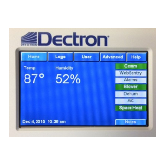
Temperatures, room air and pool water, could be displayed in either Fahrenheit (default) or Celsius (optional) degrees. Date&Time At the bottom of the page, you will see the current date and time. TOUCHSCREEN 2.1 SEPTTEMBER 12, 2017... -
Page 9: Status
Access to advanced settings and features Advanced Context sensitive help presenting information related to Help the viewed page While Home button function is simple and rather straight forward, other buttons are multi-layered and more complex. TOUCHSCREEN 2.1 SEPTTEMBER 12, 2017... -
Page 10: Logs
SD card at regular intervals when the display is not being used. Pressing this button will force a full backup of all log data to the SD card Figure 5. Logs page TOUCHSCREEN 2.1 SEPTTEMBER 12, 2017... -
Page 11: User
Setpoint page (Figure 7): Parameters buttons and their respective current setpoints value will be displayed (per system current configuration); You can press Back button at any time to return to previous (in this case – User) page. TOUCHSCREEN 2.1 SEPTTEMBER 12, 2017... - Page 12 (default, max and min value), area below it will provide selected parameter definition (“Help”) Keypad on the right side allows to select, enter or correct the value. Figure 8. Room Temperature setpoint adjustment page. TOUCHSCREEN 2.1 SEPTTEMBER 12, 2017...
-
Page 13: System Restart And Display Restart
The Advanced page allows to view and adjust system’s control settings and configurations. CAUTION! Improper/incorrect Advanced settings may cause system malfunction and premature failure! Once you click Advanced button, before allowing to proceed, touch display will issue respective warning. TOUCHSCREEN 2.1 SEPTTEMBER 12, 2017... - Page 14 Touch display settings (temperature degrees’ type TouchScreen preference, date and time format, display password etc.). Settings are stored only on the SD card and are unique for each display. TOUCHSCREEN 2.1 SEPTTEMBER 12, 2017...
- Page 15 (Advanced). For example, if system is not configured to have a pool heating, all pool heating related features would not be shown (pool water temperature setpoint in User menu, Pool water temperature sensor reading in Readouts, Pool Heat status indicator in Status etc.) TOUCHSCREEN 2.1 SEPTTEMBER 12, 2017...
-
Page 16: Help
When browsing the Alarm Log, you can tap the Help button to the right of each alarm entry to get a description of the alarm (see Figure 10 below): Figure 10. Alarm Log with Help feature TOUCHSCREEN 2.1 SEPTTEMBER 12, 2017... -
Page 17: Notes
Use the message area for the note itself. The main notes page shows a list of names of people that have left a note. Tap on the View button to read the note. Figure 11. Notes page TOUCHSCREEN 2.1 SEPTTEMBER 12, 2017... -
Page 18: Service Mode. Home Page Layout And Navigating
The components are divided into groups: Ventilation (main blower, exhaust fans, outdoor air dampers and heat recovery), Heating (both space heating and pool water heating), and Compressor (one menu button for each compressor circuit, if current system is configured for two compressors). TOUCHSCREEN 2.1 SEPTTEMBER 12, 2017... - Page 19 Figure 14 shows main blower speed signal being set to 35%; if needed, this value could be increased (by pressing” +”) or decreased (by pressing “-“). Pressing “Reset” will set it to zero. TOUCHSCREEN 2.1 SEPTTEMBER 12, 2017...
-
Page 20: Service Mode - Commissioning
Service button. It allows for access to following features: • Commission – allows to commission/de-commission the system. Systems, delivered from Dectron Company are set to be Non- commissioned (decommissioned) – this ensures that system would not convert to Normal mode after restart or power up without being commissioned by start up agent. -
Page 21: Touch Display - Sw Update, Calibrating And Troubleshooting
To install the SD card, insert the card into the slot with the contacts facing towards you (see Figure 15 below). Insert the SD card until you hear a click and it locks into place. Figure 15. SD Card Orientation TOUCHSCREEN 2.1 SEPTTEMBER 12, 2017... -
Page 22: Sd Card - File Structure
It also contains an optional NOTES folder where all notes are stored (if you have saved any notes). BACKUP This is where all system backups are stored. Backups are saved with the filename YYYYMMDD.BAK where YYYY is year, MM is month and DD is day. TOUCHSCREEN 2.1 SEPTTEMBER 12, 2017... -
Page 23: Updating Firmware
One file for each log type. The log entries are stored in separate files in time stamped sub folders. Contents of these sub folders can be saved to your PC and sent to Dectron for analysis. FIRMWARE Contains all saved firmware files accessible from the Firmware Update page. -
Page 24: Updating Menu And Help Files
Most of the menu and help system displayed on the touchscreen is controlled by files stored on the SD card. As Dectron releases new versions of the control software, new settings will be added and other ones will be removed. There will be improvements to the help system based on feedback from users. -
Page 25: Touch Display Calibration
Figure 16). You will be asked to tap the four corners and then one more time anywhere on the screen to save the calibration data. Please take your time and tap right in the center of each circle to get the most accurate calibration. TOUCHSCREEN 2.1 SEPTTEMBER 12, 2017... -
Page 26: Touch Display Troubleshooting
You may need to verify and/or adjust certain parameters in the system software via direct communication via Supervisaire control board – you’d need special communication operator panel for that (contact Dectron Service group for support). Verify TouchScreen Port Configuration Select Advanced, TouchScreen and then Serial Interface. Default configuration is baud rate 57600 and response time 1000 ms. - Page 27 If JCOM (6 & 7) is being used, remove wires before using the RJ-45 socket. You can also wire TouchScreen display to J8 using port D. TOUCHSCREEN 2.1 SEPTTEMBER 12, 2017...
Need help?
Do you have a question about the TOUCHSCREEN 2.1 and is the answer not in the manual?
Questions and answers