
Related Manuals for TAC Xenta 411


Summary of Contents for TAC Xenta 411
- Page 1 TAC Xenta I/O modules 24 V AC Comm (19-40 V DC) G G0 C1C2 1 2 3 4 5 6 7 8 9 10 TAC Xenta 452 MAN 1 MAN 2 0 - 10V 0 - 10V AUTO AUTO RS232...
- Page 3 The descriptions of these were previously included in the manual “TAC Xenta 400 Handbook”, but as the handbooks for the TAC Xenta 300 and 401 were merged, the sections describing the I/O modules were assembled in a separate manual. The purpose of this is to simplify adding new modules to the new manual.
- Page 4 1999-11-20 0-004-7771-1 TAC Xenta 471 and 491/492 added. 2000-09-01 0-004-7771-2 Operation temp. for Operation TAC Xenta 421XT and 422XT added. M F 2003-06-25 Part nos. for TAC Xenta 421XT and 422XT added 2003-06-25 4 (36), 0-004-7771-2 (GB) TAC AB, 2003-07-01...
-
Page 5: Table Of Contents
400 I/O modules This document contains proprietary information of TAC AB and is made available solely to those who operate and maintain TAC AB equipment. Disclosure, reproduction or use of either the documents or the information contained herein for any other purpose is strictly prohibited. - Page 6 TAC Xenta 400 I/O modules Contents 6 (36), 0-004-7771-2 (GB) TAC AB, 2003-07-01...
-
Page 7: Introduction
Introduction 1.1 TAC Xenta 400 I/O modules The TAC Xenta 400 is a series of input/output modules designed to be connected to the TAC Xenta 300 or 401 type controllers. The installation procedures and technical data are similar between the different modules. -
Page 8: More Information
TAC Xenta 400 I/O modules 1 Introduction 1.3 More information The TAC Xenta 400 I/O modules and the other TAC Xenta units are also described in the following documents: • the “TAC Xenta 300 and 401 Handbook”, part no. 0-004-7768 •... -
Page 9: O Modules In The Tac Xenta 400 Series
12 13 14 15 16 17 18 Operator panel TAC Xenta units; the Operator panel, the TAC Xenta controller (here: 401) and an I/O expansion module A number of controllers and I/O modules can form a local network and exchange data. - Page 10 TAC Xenta 400 I/O modules 2 I/O modules in the TAC Xenta 400 series The I/O modules are used as expansion modules for the TAC Xenta controllers, connected to these via the common TP/FT-10 network. The modules have different I/O configurations to suit different applications.
-
Page 11: Configurations
TAC Xenta 400 I/O modules 2 I/O modules in the TAC Xenta 400 series 2.2 Configurations The I/O modules of the TAC Xenta 400 series can be used in different configurations, for example: • Together with a stand-alone controller. • With controllers and OPs in a network. - Page 12 TAC Xenta 400 I/O modules 2 I/O modules in the TAC Xenta 400 series 12 (36), 0-004-7771-2 (GB) TAC AB, 2003-07-01...
-
Page 13: Technical Description
G G0 C1C2 1 2 3 4 5 6 7 8 9 10 Terminals 1-4 of the TAC Xenta I/O modules 3.1.2 Indicators and Service pin On the front, there is a small hole through which the Service pin may be activated, as well as two LED indicators, one red and one green. -
Page 14: Technical Data, Common To All
(with LED indicators and DO override) ....0-073-0243 Electronics part TAC Xenta 422XT ....... 0-073-0244 Electronics part TAC Xenta 451 (4 UI, 4 TI, 2 AO) ..0-073-0281 Electronics part TAC Xenta 452 (4 UI, 4 TI, 2 AO) (with LED indicators and AO override) ....0-073-0283 Electronics part TAC Xenta 471 (8 UI, mA/VDC) .. -
Page 15: The Tac Xenta 411/412 Digital Input Module
The modules have ten digital inputs and these inputs can also be used as pulse counters. In addition, the TAC Xenta 412 is equipped with LED status indicators, one for each digital input. The LED colors, red or green, are individually selectable, by setting switches under the front cover. -
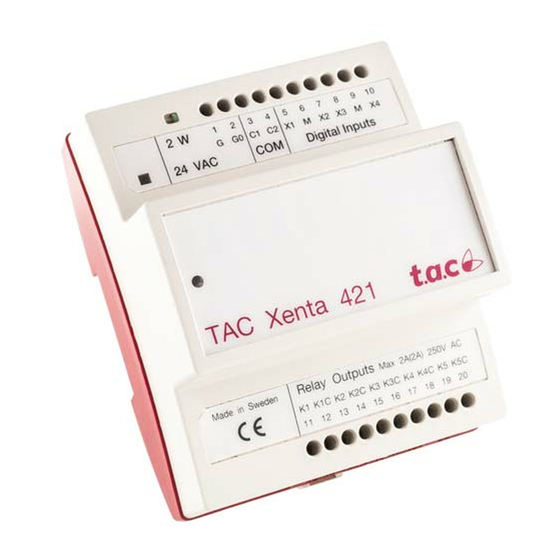
Page 16: The Tac Xenta 421/422 Digital Input And Output Module
11 12 13 14 15 16 17 18 19 20 K1 K1C K2 K2C K3 K3C K4 K4C K5 K5C max 230 V AC TAC Xenta 421/422 terminals and TAC Xenta 422 relay output switches and Indicators Type TAC Menta Block type Terminal ref. - Page 17 Quantity ..................4 Voltage across open contact ..........33 V DC Current through closed contact ..........4 mA Pulse input duration (TAC Menta CNT block) ....min. 20 ms Digital outputs (K1–K5): Quantity ................... 5 Control voltage, relay outp. protected by a max. 10 A fuse, 230 V AC Control current ..............
-
Page 18: The Tac Xenta 451/452 Analog Input And Output Module
11 12 13 14 15 16 17 18 19 20 Y1 M Y2 B1 M B2 B3 M B4 Thermistor inputs TAC Xenta 451/452 terminals and TAC Xenta 452 Analog output override controls and Indicators Type TAC Menta Block type Terminal ref. - Page 19 –as Digital Inputs; Voltage across open contact ........max. 28 V DC Current through closed contact ..........4 mA Pulse input duration (TAC Menta CNT block) ....min. 80 ms –as Thermistor Inputs; Supply voltage ..............0.6 V DC TAC thermistor sensor ........1800 ohms at 25 °C –as Voltage Inputs;...
-
Page 20: The Tac Xenta 471 Analog Input Module
TAC Xenta 400 I/O modules 3 Technical description 3.5 The TAC Xenta 471 Analog Input module The module has eight universal analog inputs (U). The analog inputs can independently be used for current input or as voltage inputs. The current inputs use either the internal power (24V DC) or the external power (M). -
Page 21: The Tac Xenta 491/492 Analog Output Module
Manual control 11 12 13 14 15 16 17 18 19 20 Y4 M Y5 M Y6 M Y7 M Y8 M TAC Xenta 491/492 terminals and manual control of the TAC Xenta 492 TAC AB, 2003-07-01 0-004-7771-2 (GB), 21 (36) - Page 22 Control voltage ............. 0–10 V DC Control current, short-circuit proof ......max. 2 mA Deviation ................max ±1% Manual control of the analog outputs (TAC Xenta 492 only): Quantity ..................8 Switch positions ............MAN, AUTO Control interval ..............0–10 V...
-
Page 23: Installation
The enclosure is designed so that electrical installation can be carried out using the screw terminals of the terminal part, when mounted on a DIN rail or wall. The terminal part and the electronics part of the TAC Xenta I/O module Ø 4.0 TAC Xenta 300 16.1... -
Page 24: Electrical Installation
For the Xenta 400, this is only applicable to the relay outputs of the I/ O modules. All equipment connected to the TAC Xenta units must comply with the following standards: - EN 60 742 (or other relevant safety standard; for example ETL listing UL 3111-1, first version and CAN/CSA C22.2... - Page 25 (FORTA) wire 4–20 mA Basic circuit diagram for cabinet connections of TAC Xenta 451/452 I/O modules A corresponding diagram for the TAC Xenta 471 is shown on the next page. TAC AB, 2003-07-01 0-004-7771-2 (GB), 25 (36)
- Page 26 Basic circuit diagram for cabinet connections of TAC Xenta 471 I/O module When connecting G0 to ground, each TAC Xenta unit must have its own connection to the ground rail, i.e. jumpers cannot be used for the G0 terminals.
- Page 27 ZS 101-105 F0 F1 F2 F3 G0 G C2 C1 1 2 3 4 5 6 7 8 Basic circuit diagram for connecting Wall Module ZS 101–105 to TAC Xenta 400 I/O modules TAC AB, 2003-07-01 0-004-7771-2 (GB), 27 (36)
-
Page 28: Cables
The max. wire length in one segment depends on the type of wire and the topology, see the table below. The wires are not polarity sensitive, but must be a twisted-pair. For more details, please refer to the ”TAC Xenta Network guide”. One of the following cable types must be used: Cable Max. - Page 29 TAC Xenta 400 I/O modules 4 Installation If a shielded communication cable is used, the shield must be grounded at one point only. Redundant wires (second pair of Siemens J-Y(st)Y) are cut at the end of the shield. Communication cable,...
-
Page 30: Commissioning
4.3 Commissioning Commissioning of the I/O modules is always carried out together with the base units (TAC Xenta controllers) that they belong to. The procedure is therefore described in the TAC Xenta 300 and 401 manuals. 30 (36), 0-004-7771-2 (GB) -
Page 31: Index
TAC Xenta 400 I/O modules Index Index Analog Input and Output Network 28 module 18 network 9 Analog Input module 20 Analog Output module 21 Part numbers 14 B1–B4 19 service pin 13 C1 and C2 28 cabinet 25 TAC Xenta 400 7... - Page 32 TAC Xenta 400 I/O modules Index 32 (36), 0-004-7771-2 (GB) TAC AB, 2003-07-01...
-
Page 33: Reply Form
TAC AB helpdesk@tac.se Helpdesk Jägershillgatan 18 SE-213 75 MALMÖ Sweden Reply form I have found the following errors and/or unclear descriptions in the “TAC Xenta 400 I/O modules” (part number 0-004-7771-1 (GB)): On page:................................................................................................ On page:................................................................................................ - Page 34 TAC Xenta 400 I/O modules Reply form TAC AB, 2003-07-01...
- Page 36 TAC AB, Jägershillgatan 18, SE-213 75 MALMÖ, SWEDEN, +46 40 38 68 50 (switchboard), www.tac.com...
Need help?
Do you have a question about the Xenta 411 and is the answer not in the manual?
Questions and answers