
Summary of Contents for PowerWave AR1200
- Page 1 A R S T A N D A R D R E P E A T E R D A S A R S T A N D A R D R E P E A T E R I N S T A L L A T I O N A N D S E R V I C E M A N U A L Installation and Service Manual 044-05250 Rev B December 2007...
- Page 2 This Powerwave product is designed to operate within the Normal Operating (typical operating) ranges or con- ditions specified in this document. Operation of this equipment beyond the specified ranges in this document may cause (1) spurious emissions that violate regulatory requirements;...
- Page 3 AR Standard Repeater Revision Record Revision Record Revision Letter Date of Change Reason for Change August 2005 Original VD203 66 February 2007 Document number changed to 044-05250 and manual updated December 2007 Added additional power details and updated front cover 044-05250 Rev B...
- Page 4 This Page Intentionally Left Bank 044-05250 Rev B...
-
Page 5: Table Of Contents
Table of Contents Abbreviations............... . vi Chapter 1 - Product Description Introduction . - Page 6 Table of Contents AR Standard Repeater Chapter 2 - Controls, Connections and Indicators Introduction ............... .2-1 Front Cover LED Indicators .
- Page 7 AR Standard Repeater Table of Contents Return For Service Procedures ............4-11 Obtaining an RMA.
- Page 8 1-2 Powerwave AR Standard Repeater ........
- Page 9 AR Standard Repeater List of Tables List of Tables 2-1 LED Indicators ..............2-2 2-2 CHE PCBA Connectors .
-
Page 10: Abbreviations
Abbreviations AR Standard Repeater Abbreviations The following list of abbreviations are used throughout this manual, the software, and the repeater: AGCAutomatic Gain Control ALIAlarm Interface AMPSAdvanced Mobile Phone Service BABooster Amplifier BeOBeryllium Oxide BMUBase Station Master Unit BSBase Station, BS antenna = towards the base station BSABand Selective Amplifier BSelBand Selective BTSBase Transceiver Station... - Page 11 AR Standard Repeater Abbreviations NOCNetwork Operations Center OCMOptical Converter Module OMSOperation and Maintenance System PCNPersonal Communication Network (same as DCS) PCSPersonal Communication System POIPoint of Interconnect PSMPower Supply Module PTFEPolytetrafluoro Ethylene (Teflon) R2RRepeater-to-Repeater RCIRemote Control Interface RCURemote Control Unit RCMRF Converter Module RFRadio Frequency RIARepeater-to-Repeater Adapter RMURemote Master Unit...
- Page 12 Abbreviations AR Standard Repeater This page intentionally left blank viii 044-05250 Rev B...
-
Page 13: Chapter 1 - Product Description
Powerwave repeater system understand and follow the below points. • Powerwave repeaters are designed to receive and amplify signals from one or more base stations and retransmit the signals to one or more mobile stations. And, also to act the other way round, that is to receive signals from one or more mobile stations, amplify and retransmit the signals to the base stations. -
Page 14: Warning Signs
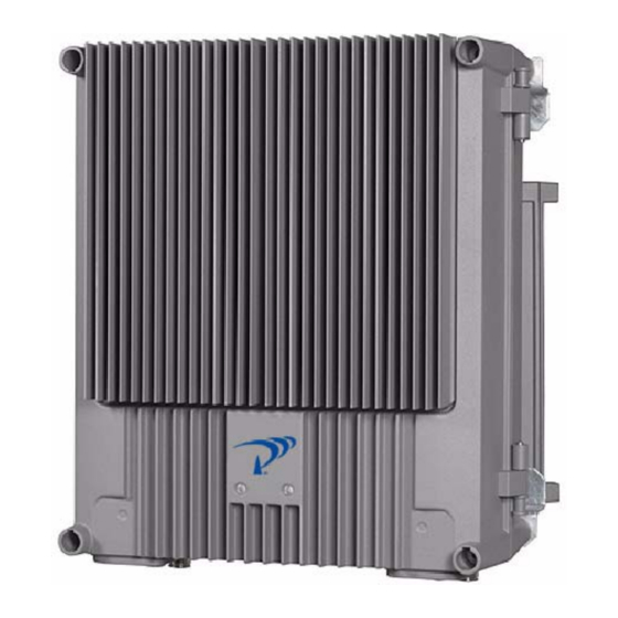
If you must handle the PCBAs or uninsulated conductor surfaces, use ESD protective equipment or first touch the chassis with your hand. Never let your clothes touch PCBAs or uninsulated conductor surfaces and always store PCBAs in ESD-safe bags. Overview Figure 1-1 Powerwave AR Standard Repeater 044-05250 Rev B... -
Page 15: Repeaters With Rf / Rf Transmission
Overview AR Standard Repeater Powerwave AR repeaters work as bi-directional on-frequency amplifiers used to fill out uncovered areas in wireless mobile systems such as base station fringe areas, tunnels, business, convention centers, airports and industrial buildings. A repeater receives, amplifies and transmits signals to/from a base station to/from mobile stations with both directions being served simultaneously. -
Page 16: Repeater Master Unit (Rmu)
AR Standard Repeater Sub Unit Overview connected to Fiber Optic Repeaters (FORs) and WRHs by using WDMs and splitters. FORs and WRHs can be fed in parallel with double or single fiber optic cables. Up to eight FORs and WRHs can be fed if the BMU is equipped with a high cover and two FONs. The BMU is also available as a 19"... -
Page 17: Band Selective Amplifier Pcba (Bsa)
Sub Unit Overview AR Standard Repeater Band Selective Amplifier PCBA (BSA) The BSA is used for BSel operations. BSel repeaters can handle multi-carriers over a wide band through the use of an adjustable bandwidth. Each repeater band requires two BSAs and two PAs;... -
Page 18: Directional Coupler (Dc)
• Interface for FLI, fiber optic network • Battery backup with charger The FON can be installed in all Powerwave repeaters Power Supply Unit (PSU) A PSU is located in the lower center of the cabinet and, if configured, in the lower center of the high cover. -
Page 19: Repeater-To-Repeater Interface Adapter (Ria)
Sub Unit Locations AR Standard Repeater Repeater-to-Repeater Interface Adapter (RIA) The RIA is required for R2R networking if a previous CU PCBA (K103/2), is used. This PCBA is located in the upper left part of the shielded DIA frame. R2R functionality is included starting in the CU PCBA part # K103/3. -
Page 20: Csel High Power Cdma/Wcdma Repeater
AR Standard Repeater Sub Unit Locations LNA - UL LNA - DL ALI/RCI (RCU) Figure 1-4 CSel CDMA/WCDMA Repeater Sub Unit Locations CSel High Power CDMA/WCDMA Repeater A cabinet for a CSel High Power CDMA or WCDMA repeater can be equipped with two pair of CSAs and PAs, one pair for the DL and one pair for the UL. -
Page 21: Bmu
Sub Unit Locations AR Standard Repeater LNA - UL LNA - DL ALI/RCI (RCU) Figure 1-6 BSel Repeater Sub Unit Locations The BMU has the donor and service cable ports opposite the ports of other repeaters. A cabinet for a BMU has no CU PCBA and no amplifier PCBAs but instead contains a FOU with a FON and a DPX. -
Page 22: Rmu
AR Standard Repeater Sub Unit Locations Figure 1-8 Optical Converter Module (OCM) Figure 1-9 illustrates an example of an RMU for BSel operation. This unit has a FON and a DPX. By adding WDMs and splitters to the FOU up to four FORs can be fed in parallel by a BMU with double or single fiber communication. -
Page 23: Combined Repeater
Using Repeaters AR Standard Repeater Combined Repeater Figure 1-11 illustrates a combined CSel and BSel repeater. The CSel part is located in the cabinet and the BSel part in a high cover. This example has four bi-directional GSM channels and BSel operation. Most of the repeater models mentioned in this manual can be mixed as a combined repeater. -
Page 24: Shaded Area
AR Standard Repeater Using Repeaters Shaded Area In this example, we have a valley that is shaded by the hills surrounding it. There is a base station 5 kilometers away but the lowest signal strength in the valley is less than –100dBm. A 42 meter mast used for other purposes is located on one of the hills and is available for a repeater installation as illustrated in Figure 1-12. -
Page 25: Sports Arena
Using Repeaters AR Standard Repeater Sports Arena In this example, we have a 2000 spectator sports arena with a metallic roof that had an indoor signal strength too low to provide fair service in most parts of the arena. The nearest base station was 8 kilometers away and was equipped with only one carrier. -
Page 26: Fiber Optic Distribution Networks
AR Standard Repeater Using Repeaters Fiber Optic Distribution Networks Fiber optic networks are setup identically to data networks by using either a star or daisy-chain configuration. The two examples below illustrate part of a road covered by a BMU or RMU and four FORs. -
Page 27: Multi-Operator Configurations
Using Repeaters AR Standard Repeater Multi-Operator Configurations Multi-operator systems require the use of Point of Interconnects (POIs), RF Combining Modules (RCMs) and OCMs as illustrated in Figure 1-16. In this simple example, two operators have two sectors each. Each sector is connected to a POI and then to a RCM. The RCM is interconnected with an OCM via coaxial cables. - Page 28 AR Standard Repeater Using Repeaters This page intentionally left blank 1-16 044-05250 Rev B...
-
Page 29: Chapter 2 - Controls, Connections And Indicators
Chapter 2 Controls, Connections and Indicators Introduction This chapter contains descriptions of the controls, connections and indicators of the AR Standard Repeater. Front Cover LED Indicators Two LEDs are located on the front cover to provide easy identification of a fault in the repeater system. -
Page 30: Pcba Connections
AR Standard Repeater PCBA Connections Table 2-1 LED Indicators Description ALI or RCI PCBA Green LED, indicates 10V power is available and within specification POWER Yellow LED, indicates power is present and remains steady after power is switched on. FAULT Red LED, flashes for 15 –... -
Page 31: Csa Pcba
PCBA Connections AR Standard Repeater P701 Input on the CMB/DL combiner CHE3/UL (position 3 from left) P101 OUT1 on the LNA/UL low noise amplifier P701 4 channels: Input on the CMB/UL combiner 2 channels: LO on the service DPX duplex filter CHE4/UL (position 4 from left) P101 OUT2 on the LNA/UL low noise amplifier... -
Page 32: Bsa Pcba
AR Standard Repeater PCBA Connections BSA PCBA Table 2-4 lists the connectors and connections for the BSA PCABA. Coaxial connector P101 is the input port and coaxial connector P301 is the output port. The signal from this port is fed to the PA input port P4. -
Page 33: Cu Pcba
PCBA Connections AR Standard Repeater DOOR DOWN-LINK UP-LINK M ODEM ALARM ALLGON INNOVATION SWEDEN M 105 R6 PARKING FOR W5 Figure 2-3 DIA PCBA connectors and testpoints Table 2-6 DIA PCBA Connections Port Connected to CU PCBA P3, 5, 6 Not Used ALI or RCI PCBA P11 - 14... -
Page 34: Lna
AR Standard Repeater PCBA Connections TEST TEST -30 dB -30 dB -20 dB -20 dB Figure 2-4 Directional Couplers Table 2-7 Directional Coupler Connections Service DC Port Connected to ANT on the service DPX filter TEST -30dB Test port for the downlink output signal (no directivity) MS -20dB Not used Service antenna or RF service cable... -
Page 35: Dpx
PCBA Connections AR Standard Repeater ATT +7V OUT2 OUT1 OUT1 OUT2 +7V ATT Figure 2-5 Low Noise Amplifiers Table 2-8 Low Noise Amplifier Connections LNA/UL Port Connected to OUT LOW IN on the LNA/UL in the cover, if equipped LO on the service DPX duplex filter. ATT +7V P23 on the DIA PCBA. -
Page 36: Fou
AR Standard Repeater PCBA Connections CSel GSM repeater: 4 channels: Output on the CMB/DL 2 channels: P701 on the CHE1/DL CSel CDMA/WCDMA and BSel repeaters: P5 on the PA/DL High power CDMA/WCDMA repeater: P4 on the BA/DL PCBA in the cover IN on the LNA/UL P2101 on the WBA PCBA Donor DPX Port... -
Page 37: Fon
PCBA Connections AR Standard Repeater P115 P109 P105 P111 P116 P108 P102 P102 P103 P106 P104 P113 P114 P110 Beryllium oxide hazard P101 P101 P130 P112 Figure 2-6 FOU Table 2-10 FOU/DPX connections on the donor side (BMU or RMU) Port Connected to BMU: BS -20dB on the donor (BS) DC... -
Page 38: Fon Led Indicators
AR Standard Repeater PCBA Connections WARNING: There are two attenuators at the P101 port on the FON that may contain Beryllium oxide (BeO), which is poisonous. The attenuators are found inside the shield. P102 P115 P109 P105 P111 P116 P108 P103 P106 P104... -
Page 39: Psu
PCBA Connections AR Standard Repeater Table 2-12 FON Connectors Port Type Description P101 Electrical RF input port (to the optical TX port) P102 Electrical RF output port (from the optical RX port) P103 Electrical RF output port (15dB below the P102 port) DIN/APC Optical input port (to the P102 and P103 RF ports) DIN/APC... -
Page 40: Power Supply Unit (Psu)
AR Standard Repeater PCBA Connections DOOR DOWN-LINK UP- LINK TEST TEST M ODEM ALARM -30 dB -30 dB -20 dB -20 dB A LLGON INNOV ATION SWEDEN M 105 R6 PARKING FOR W5 POWER SUPPLY UNIT Figure 2-8 Power Supply Unit (PSU) Table 2-13 PSU Connectors Port Description... - Page 41 PCBA Connections AR Standard Repeater Alarm Port (15-pin D-sub female) - Used for external alarm sensors and alarm equipment. It is located on the DIA to the left in the cabinet. The port has four alarm inputs, EAL1 – EAL4, and two alarm outputs. The four alarm inputs are low-level inputs with common ground (AIC).
-
Page 42: Software And Hardware Compatibility
SA102 08/x This information is accurate as of 1/31/2007. As new versions of hardware and software are released without prior noticing, contact your Powerwave sales representative if in doubt about the latest revision status. For detailed information, refer to the release notes for the CU software to be downloaded (normally found in the readme.txt file provided with the program files). -
Page 43: Chapter 3 - Installation
AR Standard Repeater. Site Survey Powerwave recommends that a site survey be performed prior to equipment ordering or installation. Performing a detailed site survey reduces or eliminates installation and turn-up delays. Pay particular attention to power plant capacity, cooling needs, floor space, and RF/ DC cabling/breaker requirements. -
Page 44: Mounting Bracket
Mounting AR Standard Repeater Ø14 Figure 3-1 Mounting bracket Normally, the AR repeater is mounted on a wall, pole or mast. Figure 3-2 illustrates the installation of the mounting bracket on a wall using four fixing screws and a locking screw. Figure 3-2 Mounting bracket installation on wall 044-05250 Rev B... -
Page 45: Attaching The Bracket To A Pole
AR Standard Repeater Mounting Figure 3-3 illustrates the installation of the mounting bracket on a pole using two 5.7” (144mm) U-shaped clamps and a locking screw. Figure 3-3 Attaching the bracket to a pole Figure 3-4 illustrates a mast installation using two 11.8” (300mm) bar-shaped clamps and no locking screw. -
Page 46: Connections
Connections AR Standard Repeater After installing the mounting bracket, hang the repeater on the upper supports, as illustrated in Figure 3-5. Tighten the upper and lower mounting screws to secure it into place. Locking cylinders, used to prevent unauthorized removal of the repeater, can be inserted and locked with a key after the lower screws have been tightened. -
Page 47: Rf-To-Rf Repeater Connections
AR Standard Repeater Connections WARNING: Prior to applying power to an AC repeater, verify that the AC voltage selection switch, located to the right of the power plug recepticle, is set to the appropriate voltage level (115 VAC or 230 VAC). An incorrect setting may damage the equipment. This AC version of this product is also designed to be able to use IT power systems with phase to phase voltage (230 V). -
Page 48: Bmu Rf To Fiber Optic Connections
Connections AR Standard Repeater BMU RF to Fiber Optic Connections Figure 3-7 illustrates a BMU with separate TX/RX fiber optic cables to one FOR. By using WDMs and OSPs, up to four FORs, or eight using a high cover, can be fed in parallel by one BMU with double or single fiber optic cables. -
Page 49: Rmu Rf To Fiber Optic Connections
AR Standard Repeater Connections RMU RF to Fiber Optic Connections Figure 3-8 illustrates an RMU for donor antenna and separate TX/RX fiber optic cables to one FOR. By using WDMs and OSPs, up to four FORs, or eight using a high cover, can be fed in parallel by an RMU with double or single fiber communication. -
Page 50: For Rf To Fiber Optic Connections
Connections AR Standard Repeater FOR RF to Fiber Optic Connections Figure 3-9 illustrates a FOR for service antenna and separate TX/RX fiber optic cables from a BMU. By adding WDMs and OSPs, a number of FORs can be fed by one BMU with double or single fiber communication. -
Page 51: Optional Connections
AR Standard Repeater Optional Connections Optional Connections Alarms Alarm signals from external sensors are received by an ALI or RCI which forwards them to the CU. The RCI is used if the repeater has an RCU. The software on the CU can activate acoustic or visual alarms or direct the alarm to the P33 alarm port for forwarding via an RCU to an OM-Online or OMS workstation. -
Page 52: Wire Link Interface (Wli) Network (Ip To R2R)
AR Standard Repeater Wire Link Interface (WLI) Network (IP to R2R) Two types of WLI networks are available for the Powerwave repeaters: Internet Protocol (IP) and Repeater-to-Repeater Link (R2R). For R2R networks: If the repeater has a previous CU PCBA model (K103/2), then a RIA PCBA is required. Further information about the IP and R2R network is located in the OM-Online User Manual . -
Page 53: Main Power Breakdown Relay
AR Standard Repeater Optional Connections Main Power Breakdown Relay To be able to distinguish PSU faults from power failure, a main power breakdown relay can be used. This relay is not included in the AR repeater and has to be mounted outside the repeater cabinet. -
Page 54: 21-60 Volt Dc Psu Installation
Optional Connections AR Standard Repeater 21-60 Volt DC PSU Installation The 115/220 VAC PSU can be replaced with a 21 to 60 VDC DC PSU Figure 3-14 illustrates the location of the mounting screws and power connectors of the PSU and Table 3-6 lists the replacement procedure. -
Page 55: Commissioning
AR Standard Repeater Commissioning Commissioning Before proceeding, carefully read the Safety section and check all connections made during the installation. To fulfill the IP65 weather protective requirements, ensure cable strain relief bushings are properly tightened. Also, ensure gaskets at cable inlets and on the cabinet are properly fitted and not damaged. -
Page 56: Measuring Output Signal Levels
Measuring Output Signal Levels AR Standard Repeater Measuring Output Signal Levels Uplink and downlink output signal test ports are located on the DCs at the donor and service antenna connectors, provided the unit is configured with optional DCs. These test ports are labeled TEST -30dB as illustrated in Figure 3-16 and are intended for signal measuring using a spectrum analyzer. -
Page 57: Chapter 4 - Maintenance
The sections that follow contain a list of problems that could occur and a few suggested actions that can correct the problem. If the suggested corrective action does not eliminate the problem, please contact your Powerwave field representative or help line for further instruction. - Page 58 Troubleshooting AR Standard Repeater Critical PSU2 in the cover does not work properly. A sum sig- nal from the PSU2 indicates that at least one voltage output has dropped. If no mains breakdown relay is used, then the alarm will also be sent at mains break- down.
- Page 59 AR Standard Repeater Troubleshooting Inst. unit Error Compared to the last power on, the CU lacks at least lost one hardware unit. EEPROM Error EEP read or write fail. Data cannot be written or read error from the EEPROM on the CU PCBA. User parame- ters are stored in the EEPROM.
- Page 60 Troubleshooting AR Standard Repeater External Exter- Config External alarm input EA1 active more than 1 second. alarm 1 Ceasing External alarm input EA1 no longer active. External Exter- Config External alarm input EA2 active more than 1 second. alarm 2 Ceasing External alarm input EA2 no longer active.
- Page 61 AR Standard Repeater Troubleshooting Ceasing The cause of the alarm has ceased. Battery RCU, Error The backup battery on the RCU or the FON PCBA fault does not work properly. Suggested remedy: Check charger cables or replace battery. Ceasing The cause of the alarm has ceased. RF block- Chan- Error...
- Page 62 Troubleshooting AR Standard Repeater Error R2R HW failure because the CU cannot read the MAC-ID or any other HW error in the R2R logic. Sug- gested remedy: Replace the repeater. Error R2R HW failure because the CU cannot read the MAC-ID or any other HW error in the R2Rlogic.
- Page 63 AR Standard Repeater Troubleshooting Error A DC voltage on a FON PCBA is out of range. Sug- power gested remedy: Replace the FON PCBA. alarm Ceasing The cause of the alarm has ceased. Error Laser transmitter control loop voltage out of range. TxStable Suggested remedy: Replace the FON PCBA.
- Page 64 Troubleshooting AR Standard Repeater Param R/ CHA # Error EEPROM read or write failure on the PCBA. W error High tem- CHA # Warn- The CHA PCBA temperature is higher than 85°C. perature Error The CHA PCBA temperature is higher than 95°C. Ceasing The CHA PCBA temperature has fallen below 70°C.
-
Page 65: Field Replaceable Units
AR Standard Repeater Field Replaceable Units Not In None Repeater is moved from the operating area and the Allowed RF HW is switched on or off. Area Remarks: The Door open alarm requires an optional door switch described in the P33 Alarm Port section in Chapter 3. -
Page 66: Psu
Field Replaceable Units AR Standard Repeater To replace a PSU, proceed as described in the Table 4-4. Table 4-4 PSU Replacement Procedure Step Action Open repeater door and secure Disconnect main power plug from PSU Disconnect power cable bundle from PSU Loosen screws securing PSU using a 5mm Allen key and remove. -
Page 67: Return For Service Procedures
Repackaging for Shipment To ensure safe shipment of the unit, it is recommended that the original package designed for shipping the unit be reused. If it is not available, contact Powerwave’s Customer Service Department for packing materials. Options... -
Page 68: Rcu For Radio Communication
Options AR Standard Repeater The RCU is connected to P130 on either an RCI or FON. A jumper is required between pins 1 and 2 on the RCI if the P130 cable connector is disconnected. If a main power failure occurs, the unit has a battery with enough capacity for sending a number of alarms. -
Page 69: Gsm Subscriber Conditions
PSTN Figure 4-3 R2R network The R2R network is a Powerwave specific repeater network that can handle up to 13 nodes, one or several of which being gateway repeaters for communication with OM-Online or OMS via modem. Powerwave repeaters produced after January 2005 have the R2R functionality. -
Page 70: Protocol
7/16" Antenna Cable Connectors A 7/16" antenna cable kit is available for all the Powerwave repeaters. This kit includes 7/16" antenna connectors for UL and DL antennas mounted on two repeater cable inlet flanges and cables and connectors for connection to the DCs inside the repeater. -
Page 71: Chapter 5 - Specifications
Receiver input port return loss 14dB Power supply voltage (default) 115 VAC Power consumption, max 160 W AR1200 Family - GSM 900 Band Selective Frequency band UL 890-915 MHz Frequency band DL 935-960 MHz Number of channels Absolute group delay 6 µs... - Page 72 Introduction AR Standard Repeater AR1700 Family - GSM 900 Channel Selective Frequency band UL 890-915 MHz Frequency band DL 935-960 MHz Number of channels 1 to 8 Absolute group delay 5 µs Filter bandwidth (remotely adjustable) 200 KHz Gain adjustment range (in 1 dB steps) 55-90dB Gain (max variation –25 to +55 °C) Pass band ripple...
- Page 73 AR Standard Repeater Introduction Gain (max variation –25 to +55 °C) Pass band ripple Maximum input power (non-destructive) +13dBm Output power RMS, one carrier, DL +29dBm (+32dBm PEP) Noise figure at 85 dB gain, 25° C (typical) AR3100/3700 Family - GSM 1900 Channel Selective Frequency band UL 1850-1910 MHz Frequency band DL...
- Page 74 Introduction AR Standard Repeater AR1700/902 Family - EGSM 900 Channel Selective Frequency band UL 880-915 MHz Frequency band DL 925-960 MHz Number of channels 1 to 8 Absolute group delay <5 µs Gain adjustment range (in 1 dB steps) 55-90dB Gain (max variation –25 to +55 °C) Pass band ripple Maximum input power (non-destructive)
- Page 75 AR Standard Repeater Introduction Maximum input power (non-destructive) +13dBm Output power RMS, one carrier, DL +30dBm; Standard AR6500 Output power RMS, one carrier, UL +20dBm Output power RMS, one carrier, DL +38dBm; High Power AR6560 Noise figure at 85 dB gain, 25° C (typical) AR3400 Family –...
- Page 76 Introduction AR Standard Repeater AR4600 Family – iDEN/SMR Band Selective Frequency band UL 806-824 MHz Frequency band DL 851-869 MHz Absolute group delay 6 µs Filter bandwidth (remotely adjustable) 0.5-16.9 MHz Gain adjustment range (in 1 dB steps) 45-85dB Gain (max variation –25 to +55 °C) Pass band ripple Maximum input power (non-destructive) +13dBm...
-
Page 77: Appendix A Block Diagrams
Appendix A Block Diagrams Introduction This appendix describes the main signals paths for the different AR Standard Repeater models. CSel GSM Repeater CHE1 - DL P701 P101 OUT2 TEST –30 dB CHE2 - DL P701 P101 OUT1 CHE3 - UL MS –20 dB P701 P101... -
Page 78: Csel Cdma/Wcdma Repeater
CSel CDMA/WCDMA Repeater AR Standard Repeater The output signal from the mixer is then amplified in the PA and fed to a combiner which combines the signals from the two channels on the CSA The output signal passes a CMB and DPX before it is fed to the repeater service antenna. -
Page 79: Bsel Repeater
AR Standard Repeater BSel Repeater BSel Repeater CSA - DL LNA - DL OUT1 P101 P301 TEST –30 dB PA - DL MS –20 dB MS –20dB PA - UL CSA - UL LNA - UL P101 P301 OUT1 P34/ P130 P130 ALI / RCI... -
Page 80: Bmu
AR Standard Repeater TEST –30 dB P101 P102 MS –20 dB P130 P106 P109 P111 P112 P130 Figure A-4 BMU Block Diagram Figure A-4 illustrates a block diagram of a BMU. The BMU has to be located adjacent to the BTS as the base station antenna signal passes through the BMU. -
Page 81: Rmu
AR Standard Repeater LNA - DL BSA - DL OUT1 P101 P301 TEST –30 dB PA - DL P101 P102 PA - UL MS –20 dB BSA - UL LNA - UL P301 P101 OUT1 P34/ P130 P130 ALI / RCI Figure A-5 RMU Block Diagram Figure A-5 illustrates a block diagram of an RMU for band selective operation. -
Page 82: For
AR Standard Repeater LNA - DL BSA - DL OUT1 P101 P301 PA - DL P102 P101 PA - UL BSA - UL LNA - UL P301 P101 OUT1 P34/ P130 P130 ALI / RCI Figure A-6 FOR Block Diagram Figure A-6 illustrates a block diagram of a FOR with band selective operation. - Page 83 Tel: +852 2512 6123 Fax: +46 8 540 824 91 Fax: +852 2575 4860 www.powerwave.com ©Copyright 2007, Powerwave Technologies, Inc. All Rights reserved. Powerwave, Powerwave Technologies, The Power in Wireless and the Powerwave logo are registered trademarks of Powerwave Technologies, Inc.
Need help?
Do you have a question about the AR1200 and is the answer not in the manual?
Questions and answers