Advertisement
PO Box 1257, Wilmington, NC 28402
910-283-9791 • 800-634-9281 • Fax 910-283-6264
Home Page:
www.porta-nails.com
E-mail:
www.info@porta-nails.com
OWNER'S MANUAL
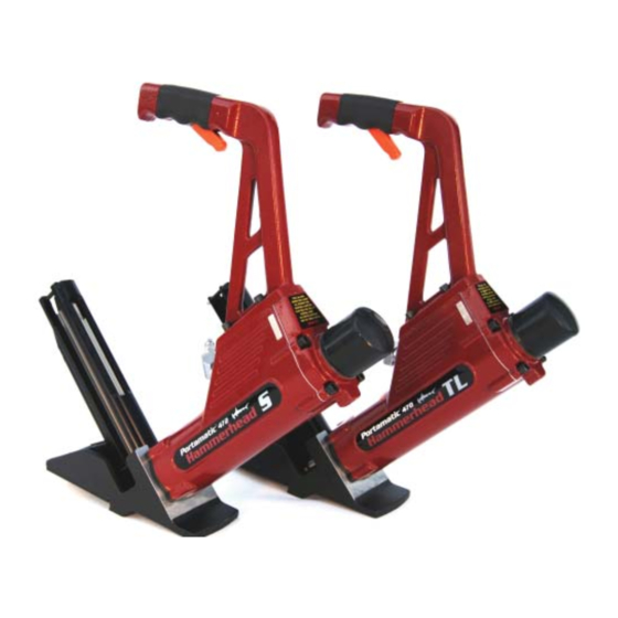
PORTAMATIC® 470 Hammerhead TL Nailer
PORTAMATIC® 472 Hammerhead S Stapler
For Tongue and Groove Solid Wood
& Hardwood Flooring
CAUTION
- Read important safety instructi ons AND operati on
instructi ons BEFORE operati ng your Pneumati c Tool.
Your new Pneumati c Tool is capable of dependable performance throughout
its lifeti me. To take full advantage of these capabiliti es you should thoroughly
understand the proper method and technique of its operati on. Therefore, we
suggest you read this manual before operati ng, and that you save it for future
reference.
For use with PORTAMATIC® 470 TL Nailers starti ng with Serial No. 07042000.
For use with PORTAMATIC® 472 S Staplers starti ng with Serial No. 05092000.
FORM P/N 470701 (4/22/2008)
Advertisement

Summary of Contents for Porta-Nails PORTAMATIC 470
- Page 1 For use with PORTAMATIC® 470 TL Nailers starti ng with Serial No. 07042000. PO Box 1257, Wilmington, NC 28402 For use with PORTAMATIC® 472 S Staplers starti ng with Serial No. 05092000. 910-283-9791 • 800-634-9281 • Fax 910-283-6264 Home Page: www.porta-nails.com E-mail: www.info@porta-nails.com FORM P/N 470701 (4/22/2008)
-
Page 2: Table Of Contents
INTRODUCTION “PNI is a proud Member of these Industry Associati ons” This fl ooring tool is a precision-built tool designed for high speed, high volume fastening. These tools deliver effi cient, dependable service when used correctly and with care. As with any fi ne power tool, for best performance the manufacturer’s instructi ons must be followed. -
Page 3: Warranty
Porta-Nails’ opti on, any defecti ve Porta-Nails branded pneumati c stapler or nailer for a period of one (1) year from date of purchase. Warranty is not transferable. Proof of purchase date required. -
Page 4: Tool Specifications
TOOL SPECIFICATIONS FASTENERS Model Length Height Width Weight PORTA-NAILS “T”: (For use with Model 470 Portamati c TL and Model 421 Portamati c Hammerhead 2) 18” 18.8” 3-1/8” 9.00 lbs. 18” 18.8” 3-1/8” 9.10 lbs. 42623 2” T-Nails (10 packages of 1000 Nails). -
Page 5: Safety Instructions
TL NAILER / S STAPLER ACCESSORIES SAFETY INSTRUCTIONS Tool Operati on Part No. Descripti on The employer is responsible for ensuring that the manufacturer’s 47075 Hammer Assy – Graphite 47061 O-ring Kit tool operati ng/safety instructi ons are available to operators. 47060 Service Parts Kit The employer and the tool operator are responsible for the safe use... - Page 6 Repair Parts and Accessories NAIL / STAPLE LENGTH DETERMINATION CHART This chart will assist you in determining the proper length of NAIL/ Tools shall be repaired or equipped only with parts or accessories STAPLE to use for various thickness of fl ooring when the sub-fl ooring that are supplied or recommended by the tool manufacturer, or with member varies as to species and thickness and for determinati on for parts or accessories which perform equivalently to those supplied or...
- Page 7 • Do not point the tool toward yourself or anyone whether it 47074 SCREW – HANDLE CAP contains fasteners or not. 47236 SCREW – MAGAZINE STAND-OFF • Do not actuate the tool unless the tool is placed fi rmly against 47241 SCREW –...
- Page 8 Actuati on System 472 – PART LISTING This tool uti lizes a dual trigger single sequenti al actuati on system. Part No. Descripti on The safety trigger located within the handle must be held depressed 47001 RAM CAP and the ram cap must be struck with the included mallet to 47002 O-RING –...
-
Page 9: Safe Operation
EXPLODED VIEW – 472 HAMMERHEAD S STAPLER in such a manner that all compressed air in the tool is discharged at the ti me the fi tti ng or hose coupling is disconnected. TOOL OPERATION BEFORE HANDLING OR OPERATING THIS TOOL READ AND UNDERSTAND THE WARNINGS CONTAINED IN THIS MANUAL. - Page 10 enough force to cause the tool to cycle. 47074 SCREW – HANDLE CAP • Keep hands and body away from the discharge area of the tool. 47036 SCREW – MAGAZINE STAND-OFF The tool may bounce from the recoil of driving a fastener and 47048 ROLLER –...
- Page 11 470 – PART LISTING causing an injury. • Do not overdrive fasteners. NOFMA states that one reason for Part No. Descripti on split tongues is over driving. 47001 RAM CAP 47002 O-RING – CAP 3, 3A 47003 SCREW – SOCKET HEAD CAP 47004 5, 5A 47005...
-
Page 12: Air Supply And Connections
AIR SUPPLY AND CONNECTIONS EXPLODED VIEW – 470 HAMMERHEAD TL NAILER FITTINGS: Install a male plug on the tool which is free fl owing and which will release air pressure from the tool when disconnected from the supply source. HOSES: Air hoses should have a minimum of 150 PSI working pressure rati ng or 150 percent of the maximum pressure that could be produced in the air system. -
Page 13: Lubrication
Replace the Cap with four (4) Socket Head Cap Screws and area of tool while the air supply is connected. • Never point the tool at anyone else. ti ghten. • Never engage in horseplay. Replace the Ram Cap. • Never pull the trigger unless nose is directed at the work. - Page 14 Frequent, but not excessive, lubricati on is required for best SERVICING ASSEMBLY / DISASSEMBLY INSTRUCTIONS performance. Oil added through the air line connecti on will lubricate Remove Ram Cap with Box Wrench. the internal parts. Use Air Tool Lubricant, Mobil Velocite #10, or Remove four (4) Socket Head Cap Screws.
-
Page 15: Maintaining The Pneumatic Tool
TROUBLE SHOOTING MAINTAINING THE PNEUMATIC TOOL (Conti nued) PROBLEM CAUSE CORRECTION When working on air tools, note the warnings in this manual and use Skipping fasteners; Broken/chipped driver Replace Driver (check extra care evaluati ng problem tools. intermitt ent feed Piston O-ring) (cont’d) Dry/dirty magazine... -
Page 16: Trouble Shooting
Hold the Piston Rod with a box wrench over its Hex End and TROUBLE SHOOTING opposite the Lock Nut. Do not use Pliers anywhere on the metal PROBLEM CAUSE CORRECTION Trigger valve housing O-ring cut or cracked Replace O-ring parts as they can damage the sealing surfaces. leaks air Remove the Lock Nut, Pin and the Driver Blade.
Need help?
Do you have a question about the PORTAMATIC 470 and is the answer not in the manual?
Questions and answers