
Summary of Contents for LogikaControl LOGIK 26-S
- Page 1 Instructions and Advices to use the electronic controller Logik 26-S ORIGINAL INSTRUCTIONS INDUSTRIAL CONTROL EQUIPMENT) 39UG FILE: E316817 Revision 1 – 04.12.2015 1/28...
-
Page 2: Table Of Contents
WARNINGS (VISUAL ALARMS) ..........................22 MESSAGES VISUALIZED INTO ALARM LIST ONLY ....................22 MAINTENANCE MESSAGES ..........................22 HOW LOGIK 26-S CONTROLS THE COMPRESSOR ................23 INVERTER OPERATION ........................25 INVERTER CONTROLLED VIA ANALOG OUTPUT 4/20mA ..................25 INVERTER CONTROLLED VIA RS485 ........................25 MASTER/SLAVE OPERATION ...................... -
Page 3: Caution
CAUTION THE LOGIK 26-S IS AN INDUSTRIAL CONTROL EQUIPMENT (NOT A SAFETY ISTRUMENT) FOR THE OPERATION OF A SCREW COMPRESSOR WITH SOFTWARE CLASS A (see EN 60730-1 and EN 60335-1). THE INSTALLATION MUST BE MADE IN ACCORDANCE TO THE LOCAL AND INTERNATIONAL STANDARDS AND REGULATIONS WHERE THE COMPRESSOR IS MANUFACTURED. -
Page 4: Technical Features
TECHNICAL FEATURES Industrial control equipment for the operation and management of screw compressors only, pollution degree 2. In accordance to EC Directives: Directive: LVD : 2014/35/UE EMC: 2014/30/UE RHOS: 2011/65/EU based on the following harmonized standards applied: SAF-EMC: EN 60730-1 RHOS: EN 50581 In accordance to UL 508 (FILE #: E316817). -
Page 5: Mounting
MOUNTING Use the drawing below as overall dimensions to mount the controller. DRILLING TEMPLATE 106 mm 161 mm WARNING TO THE WIRING OF THE CONTROLLER 1) Respect the working technical features and instructions on the electrical wiring; in special way both the cables of the temperatures probes and pressure transducers must be isolated from the power cables and proper RC filters must be placed on the contactors’... - Page 6 ELECTRICAL DRAWING AND LEGEND OF THE CONNECTIONS Revision 1 – 04.12.2015 6/28...
-
Page 7: Legend
LEGEND Terminal M1 Pole 1-2 = power supply 12Vac Terminal M2 – RS485 FOR CONNECTION MASTER/SLAVE – MULTIUNIT Pole 1 = 0 Pole 2 = D- Pole 3 = D+ Pole 4 = +15Vdc (As power supply for a Logik option) Terminal M3 Pole 1-2 = air end temperature probe Pole 3-4 = pressure transducer (pole 3 = negative –... - Page 8 EXAMPLE OF CONNECTION TO SECURITY PRESSURE SWITCH Alarm related to security pressure switch A21 is joined to the lacking phase to all the digital inputs. This is a shut off alarm: below you can find the connection drawing both to contactors 24Vac and/or 230Vac. Contactors 24Vac I°...
-
Page 9: Connection Serial Net Rs485
CONNECTION SERIAL NET RS485 To connect a serial net you have to pay carefully attention to some executive aspects: Use flexible cable, shielded, twisted 22 AWG type. Connect D- and D+ to two conductors of same couple and 0 to a third one (if available) or both conductors of a second couple. -
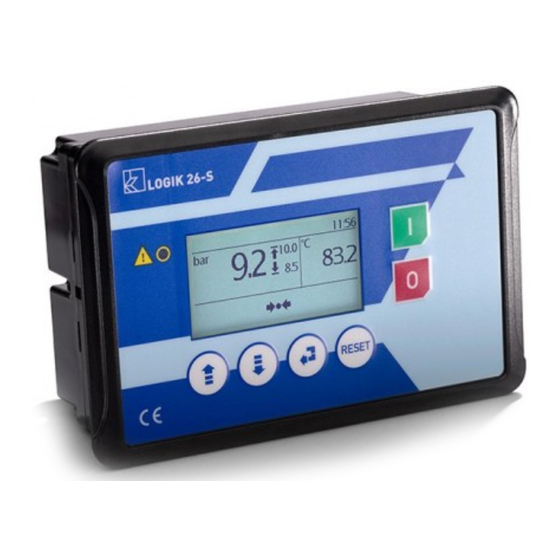
Page 10: Main Visualization
MAIN VISUALIZATION Power on and display visualizes the message “Logika Control” “Logik 26-S” for about 3 seconds, then it shift to the main visualization and the compressor is in OFF status. The pic. below shows the main visualization According the pic. above and related icons, the main visualization can be described as below: 1. - Page 11 Meaning of icons Main visualization: icons located on the upper row Condensate drain activated Multiunit operation activated Master/slave operation activated Maintenance timer over Alarm Weekly start/stop timer activated Main visualization: icons related to compressor status located lower row (centre) Compressor OFF Waiting for safety timer Pressure set, compressor running unload or stand-by Remote start/stop input open...
-
Page 12: Quick Setting Start/Stop Pressures (Enabled With Password Level3)
QUICK SETTING START/STOP PRESSURES (ENABLED WITH PASSWORD LEVEL3) To change the Start pressure push and the data starts blinking; change the value by using and/or and confirm the new one by : the data stops blinking. By the button R you can abort the modification. To change the Stop pressure, push and the data starts blinking;... -
Page 13: M2 Enter Password
ENTER PASSWORD Enter to password levels by pushing on the main visualization. Password To select the password level, use the arrow buttons and confirm Now, enter the code (2,4 or 6 digits according the level). Service 1 Use the arrow buttons to change any digit of the code, the button to shift to the digit on the right and the button R to shift back to the previous one. -
Page 14: M1-4 Compressor Setup
M1-4 COMPRESSOR SETUP In this menu you can change the general setting of the compressor. Parameters, setting range, default and password level are reported in the table below: Code Description Value Meaning Default Level Restart MAN-AUT Restart after power off: MAN (manual) – AUT (automatic) Starts/hour 0 ÷... - Page 15 Enabled if C19 is set from 2 to 4. This is the top range C19.2 Top range AI 10 ÷ 999 related to the current 20mA used to read on the main visualization the data from the inverter 0=All the alarms related to the temperature are disabled. Ventilation is operated by ON/OFF fixed cycles managed by Temperature probe the next parameters C20.1 and C20.2...
-
Page 16: M1-5 Pressures
M1-5 PRESSURES In this menu you can change the setting related to the working pressure. Parameters, setting range, default and password level are reported in the table below: Function Description Setting range Default Password level Top range transducer 15 ÷60 High pressure alarm (WP3+0,2) ÷... -
Page 17: M1-8 Inverter Rs485 (Danfoss)
M1-8 INVERTER RS485 (DANFOSS) This menu allows to visualize/set the parameters related to the inverter in case of connection via RS485 (Danfoss available only). The parameters you can set, related setting range, default and password level necessary to the visualization and modification are described in the table below: Function Description... -
Page 18: M1-9 Analog Output
M1-9 ANALOG OUTPUT This menu is visualized only if the safety pressure transducer has been configured in the menu Compressor setup (parameter C18 different from 0). The analog output is determined by a PID calculation. The analog output can be eventually connected to the electrical motor inverter or fan motor inverter. Parameter C18 must be set 1 for electric motor or 2 for fan motor. -
Page 19: M1-10 Hours Filters/Oil
M1-10 HOURS FILTERS/OIL In this menu you can visualize the maintenance timer; if you enter by a password level over 1, you can enter into the sub- menu to change and/or reset. Function Description Setting range Counter Reset Default Password level Change air filter 100 ÷... -
Page 20: M1-13 Timer Start/Stop
M1-13 TIMER START/STOP This menu allows to manage start and stop of the compressor by weekly timer. Timer start/stop Editing the timer, the display visualizes the parameters T01 “Enable timer”. If you set 1-13 YES, the display shows the link to sub-menu to enter start/stop program and T01 Enable timer “Weekly timer”. -
Page 21: Alarms
ALARMS ALARMS WITH IMMEDIATE COMPRESSOR SHUT-OFF Code Description Cause EMERGENCY STOP Emergency stop button open (IN1) MOTOR OVERLOAD Thermal motor open (IN2) THERMAL FAN Thermal fan open (IN3) NO PHASE One or more phase missed for over 300 m.s. WRONG PHASE Phase inverted DOOR OPEN IN7 open (set as come door micro-switch) -
Page 22: Warnings (Visual Alarms)
WARNINGS (VISUAL ALARMS) Code Description Cause Air end temperature over set WT2. HIGH TEMPERATURE WARNING Reset while temperature below WT2-5°C DATA LOST Loading default data AIR FILTER Air filter pressure switch closed (IN5) MULTIUNIT FAILURE No communication or Master failure: each Slave works stand alone Delta P (internal pressure –... -
Page 23: How Logik 26-S Controls The Compressor
HOW LOGIK 26-S CONTROLS THE COMPRESSOR Management of the compressor SHUT OFF Timer Wt5>0 Timer Wt5=0 WAITING Wt5 MOTOR STARTS IN SET UNLOAD FOR UNLOADING Timer Press< Timer SHUT OFF Wt5=0 P.Start Wt4=0 SET REACHED ALARM Press<P.Start Press>P.Stop LOADING The symbols into the above squares indicate the compressor status showed on the main visualization of the LCD. - Page 24 Solenoid valve operation (RL4) The symbol indicates the load solenoid valve is ON. The unload timer Wt4 can be managed according two different ways settable on C03. Wt4 set as fixed timer: when the pressure reaches stop set, the load solenoid valve (RL4) switches OFF and the timer Wt4 starts;...
-
Page 25: Inverter Operation
INVERTER OPERATION INVERTER CONTROLLED VIA ANALOG OUTPUT 4/20mA In case output 4/20mA is activated, parameter C18, the display visualizes the symbol It is visualized below pressure or temperature area according parameter C18 is set 1 (regulation on working pressure) or 2 (regulation air end temperature). -
Page 26: Master/Slave Operation
MASTER/SLAVE OPERATION The two compressors must be connected through serial connection RS232 BASE (crossing RX and TX) with length cable no longer than 10 m (for longer distance use interface RS 232/485). Set C07 as 1 (2 in case of protocol Master/Slave new allowing to connect two inverter machines). In the same menu set the time to switch Master into Slave (parameter C07.1) and the timer Slave comes into force in case Master is not enough at the first staring (parameter C07.2). -
Page 27: Warranty Terms
WARRANTY TERMS 24 (twenty-four) months from the production date printed on the label of the serial number. Temperature probe is not included in the warranty terms. Both working and technical features of the controller must be fully respected: the warranty declines if the controller has been opened or repaired by unauthorized personnel. - Page 28 Revision 1 – 04.12.2015 28/28...
Need help?
Do you have a question about the LOGIK 26-S and is the answer not in the manual?
Questions and answers
Not starting
The LogikaControl LOGIK 26-S may not be starting due to an active shut-off alarm. Possible causes include:
- Emergency stop button open (Code 01)
- Thermal motor overload (Code 02)
- Thermal fan fault (Code 03)
- Phase loss (Code 04)
- Wrong phase sequence (Code 05)
- RS485 communication failure (Code 33, 60, or 62)
Each of these alarms will stop the compressor, and the alarm message must be reset after fixing the cause by pressing the R button. Also, a GENERAL reset is only allowed when the compressor is OFF.
This answer is automatically generated