
Summary of Contents for Athena UPS APA-103T
- Page 1 USER’S MANUAL Line interactive UPS 650VA/1KVA/1.5KVA/2KVA/ 3KVA TR/5KVA TR/7.5KVA TR PM/10KVA TR PM...
-
Page 2: Table Of Contents
Uninterruptible Power Supply CONTENTS 1. INTRODUCTION ..........…………………..2. SAFTY INSTRUCTION....……...………………………..…..3. SYSTEM DESCRIPTION......……......…..4. OUTLINE DESCRIPTION......……….…………... 5. CABLE CONNECTION…………………………………………………… 6. OPERATION ..........……....... 7. TROUBLE SHOOTING GUIDE.......……….……………...… 8. OPERATION MODES OF THE UPS ....……….……………..9. COMPUTER INTERFACE ......……....... 10. SPECIFICATION…………………..……………….…..….…..….. -
Page 3: Introduction
1. INTRODUCTION 1.1 General Description The continuity of electrical power is an essential requirement for critical load operations .The Uninterruptible Power System (UPS) is designed to meet the user‘s need of present computer, server and the equipment of office automation that make the UPS more compact and less noisy. -
Page 4: Safty Instruction
1.3 Important Notices To be sure that the UPS will operate correctly, the following items should be noticed: 1. Read instructions carefully before operating the UPS. 2. UPS power connection instruction should be followed. 3. Please don‘t open the case to prevent danger. 4. - Page 5 2.2 Positioning 1. Do not put the UPS on rugged or declined surface. 2. Do not install the UPS system near water or in damp environments. 3. Do not install the UPS system where it would be exposed to direct sunlight or near heat.
- Page 6 2.4 Operation 1. Do not disconnect the mains cable on the UPS system or the building wiring socket outlet during operations since this would cancel the protective earthing of the UPS system and of all connected loads. 2. The UPS has its own internal power source (batteries). The output terminals may be live even when the UPS is not connected to the AC supply.
-
Page 7: System Description
- use only tools with insulated grips and handles. 4. When changing batteries, install the same number and same type of batteries. 5. Do not attempt to dispose of batteries by burning them. This could cause battery explosion. 6. Do not open or destroy batteries. Escaping electrolyte can cause injury to the skin and eyes. - Page 8 Buttons Description When AC plugs in (UPS is not switched on.) this LCD display light will be on. UPS operation information can be seen including UPS status, input/output voltage, 1. LCD Display input/output frequency, battery voltage, battery capacity, load capacity, temperature, and event logs. UPS output voltage and frequency can be set from it here, too.
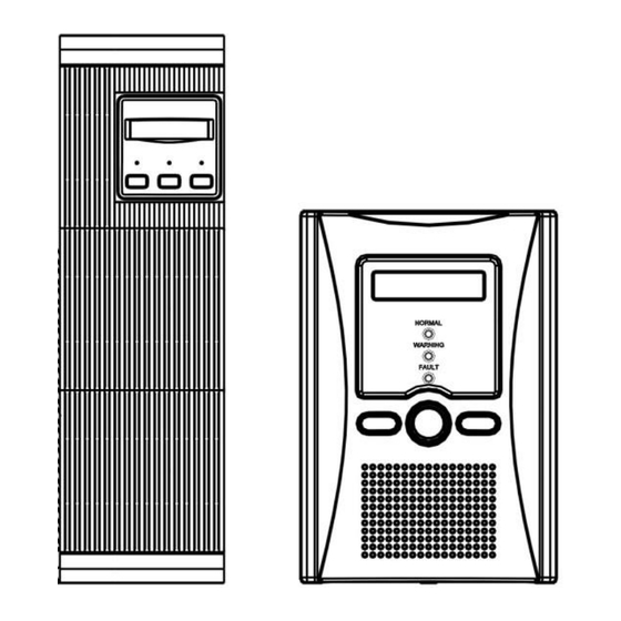
- Page 9 4. OUTLINE 4.1.Description 650VA Tower Case...
- Page 10 1KVA/ 1.5K/ 2KVA Tower Case...
- Page 11 1KVA/ 1.5KVA/ 2VA Rack & Tower Convertible Case...
- Page 12 3KVA Rack & Tower Convertible Case...
- Page 13 5KVA Rack & Tower Convertible Case...
- Page 14 7.5KVA/ 10KVA Rack & Tower Convertible Case...
- Page 15 1KVA/ 1.5KVA Rack 1U Case...
- Page 16 4.2 Back View Description 650VA Tower Case 1. USB Port 5. Fan 2. Fax / Modem Surge Protection 6. Breaker (Option) 3. Remote Control 7. Input Socket (Detachable LCD Panel, Option) 4. Output Socket (NEMA or IEC)
- Page 17 1KVA/ 1.5KVA/ 2KVA Tower Case 1. SNMP Interface Slot (Option) 5. External Battery Socket ( L ) 2. Fax / Modem Surge Protection 6. Breaker (Option) 3. Remote Control 7. Input Socket (Detachable LCD Panel, Option) 4. Output Socket (NEMA or IEC)
- Page 18 1KVA/ 1.5KVA/ 2VA Rack & Tower Convertible Case 1. RS-232 Interface Port & USB Port 6. Fan (for Multi card, Option) 2. SNMP Interface Slot (Option) 7. External Battery Socket ( L ) 3. Fax / Modem Surge Protection 8. Breaker (Option) 4.
- Page 19 3KVA Rack & Tower Convertible Case 1. RS-232 Interface Port & USB Port 6. Fan (for Multi card, Option) 2. SNMP Interface Slot (Option) 7. External Battery Socket ( L ) 3. Fax / Modem Surge Protection 8. Breaker (Option) 4.
- Page 20 5KVA Rack & Tower Convertible Case 1. RS-232 Interface Port & USB Port 6. Fan (for Multi card, Option) 2. SNMP Interface Slot (Option) 7. External Battery Socket ( L ) 3. Fax / Modem Surge Protection 8. Breaker (Option) 4.
- Page 21 7.5KVA/ 10KVA Rack & Tower Convertible Case 1. RS-232 Interface Port & USB Port 5. Fan (for Multi card, Option) 2. SNMP Interface Slot (Option) 6. Breaker 3. Remote Control 7. Terminal Block (Detachable LCD Panel, Option) 4. Output Socket (NEMA or IEC) 8.
- Page 22 1KVA/ 1.5KVA Rack 1U Case 1. RS-232 Interface Port & USB Port 4. Breaker (for Multi card, Option) 2. SNMP Interface Slot (Option) 5. Input Socket 3. Output Socket (NEMA or IEC) 6. EPO (Option)
-
Page 23: Cable Connection
5. CABLE CONNECTION 5.1 Inspection 1. The system may be installed and wired only by qualified electricians in accordance with applicable safety regulations. 2. When installing the electrical wiring, please note the nominal amperage of your incoming feeder. 3. Inspect the packaging carton and its contents for damage. Please inform the transport agency immediately should you find signs of damage. -
Page 24: Operation
6. OPERATION 6.1 Check Prior to Start Up 1. Ensure the UPS is in a suitable positioning. 2. Check if input cord is secured. 3. Make sure the load is disconnected or in the “OFF” position. 4. Check if input voltage meets the UPS rating required. 6.2 Operation Procedure Please follow the instructions below for the UPS operation. - Page 25 2. By pressing the Enter- key and the Down-key simultaneously for 3 seconds until the buzzer beeps twice, the UPS will start up and Normal LED lights up to indicate the power is from its inverter to the load. 3. When the LCD Select Down-key and the LCD Select Up-key are pressed simultaneously for 3 seconds until the buzzer beeps twice, the inverter will be turned off and the UPS is on the standby status (LCD display illuminates and Normal LED is blinking) until AC source is disconnected.
- Page 26 1.Rated Spec Menu 2.Status Menu 3.Voltage Menu 4.Frequency Menu...
- Page 27 5.Battery Status Menu 6. Output Power Menu 7.Temperature Menu 8.History Record Menu...
- Page 28 9. Output Voltage/Frequency Set Menu A. In this screen, press (4) Enter Key to enter the following steps for output voltage or frequency setting. The cursor (→) will pop up to indicate the output voltage or frequency newly selected. Use (2) Up or (3) Down-key to adjust the output voltage (220V, 230V and 240V are available for 220V system;...
-
Page 29: Trouble Shooting Guide
7.TROUBLE SHOOTING GUIDE 7.1 For LCD Model The following guideline may be helpful for basic problem solving. UPS STATUS POSSIBLE CAUSE ACTION AC utility power is normal. 1. Fan is damaged. 1. Replace the fan. UPS is running normally, 2. Unknown 2. -
Page 30: Operation Modes Of The Ups
UPS STATUS POSSIBLE CAUSE ACTION AC utility power fails .The 1. AC utility power 1. Reduce the less load is supplied by battery failure. critical load in order to power. Buzzer alarm extend backup time. 2. AC input sounds every 4 seconds. connection may be 2. - Page 31 8.2 Normal Operation There are two main loops when AC utility is normal: the AC loop and the battery charging loop. The AC output power comes from AC utility input and passes through static switch to support power to load. The battery charging voltage comes from AC utility input and converted by AC/DC charger to support battery-charging power.
-
Page 32: Computer Interface
9. COMPUTER INTERFACE 9.1 communication interface The communication interface (DB9 port) on the back of the UPS may be connected to a host computer. The port provides communication of RS-232 for monitoring software (like RUPSII or UPSilon 2000 of Megatec Company) The UPS communicates with the computer by sending out RS-232 data streams to one of the serial ports. -
Page 33: Specification
10. SPECIFICATION APA 650VA/1KVA/1.5KVA/2KVA MODEL NAME APA-650 LED APA-103T APA-153T APA-203T APA-103U APA-153U APA-103TR APA-153TR APA-203TR Capacity VA / Watt 650VA/406W 1kVA/625W 1.5kVA/938W 2kVA/1250W 1kVA/625W 1.5kVA/938W 1kVA/625W 1.5kVA/938W 2kVA/1250W Mode Type Tower Rack Tower & Rack convertible Input Nom inal Voltage... - Page 34 APA 3KVA/5KVA/7KVA/10KVA Tower & Rack convertible MODEL NAME APA-303 TR APA-503 TR APA-303 TRL APA-503 TRL APA-753 TRL APA-753 TR APA-104 TR VA / Watt Capacity 3kVA/1875W 5kVA/3125W 3kVA/1875W 5kVA/3125W 7.5kVA/4688W 7.5kVA/4688W 10kVA/6250W Tower & Rack convertible Mod e Type Tower &...
Need help?
Do you have a question about the APA-103T and is the answer not in the manual?
Questions and answers