Table of Contents
Advertisement
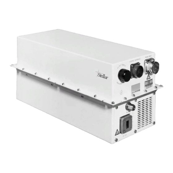
N63xx Series
Ku-Band Antenna Mount
Amplifier Product Range
Operation Manual
# 2003 e2v technologies limited
This work must not be copied in whole or in part without the prior written permission of e2v technologies limited.
e2v technologies, Waterhouse Lane, Chelmsford, Essex CM1 2QU, UK
Telephone: +44 (0)1245 493493 Fax: +44 (0)1245 492492 Internet: www.e2vtechnologies.com
Holding Company: e2v holdings limited
HBN63xx-1 Issue 8, July 2003
186/3511
Advertisement
Table of Contents

Summary of Contents for e2v Stellar N6312C
- Page 1 Operation Manual # 2003 e2v technologies limited This work must not be copied in whole or in part without the prior written permission of e2v technologies limited. e2v technologies, Waterhouse Lane, Chelmsford, Essex CM1 2QU, UK Telephone: +44 (0)1245 493493 Fax: +44 (0)1245 492492 Internet: www.e2vtechnologies.com...
-
Page 2: Safety Notes
Consult e2v technologies and the appropriate national authorities for details regarding the disposal of damaged or old TWTs and amplifiers. -
Page 3: Standards Compliance
Stellar amplifiers comply with the following requirements. Further details may be provided if necessary. EEC Directive 89/336/EEC Electromagnetic compatibility. EEC Directive 93/97/EEC Satellite earth station equipment. EEC Directive 73/23/EEC Low voltage directive e2v technologies’ quality management system is certificated to the requirements of ISO9001. HBN63xx-1, Issue 8, Page 3... -
Page 4: Customer Care
Return Procedure In the event of a Stellar product requiring return to e2v technologies: 1. Have as many of the following details as possible to hand before contacting e2v technologies. This will help us to respond promptly to your request. -
Page 5: Table Of Contents
CONTENTS SAFETY NOTES ..... . 2 STANDARDS COMPLIANCE ....3 CUSTOMER CARE . -
Page 6: Thank You For Buying Stellar
1 THANK YOU FOR BUYING STELLAR Thank you for buying a Stellar TWTA. This e2v technologies antenna mount amplifier range provides RF power amplification at up to 180 W in the Ku-band. The amplifier is: Compact Lightweight Portable 7 can run off a wide range of mains input voltages and frequencies Designed for high reliability. -
Page 7: Care Of Your Amplifier
Do not use detergents or other cleaners without consulting e2v technologies. The amplifier must be disconnected from the mains supply before cleaning. -
Page 8: Installation Considerations
3 INSTALLATION CONSIDERATIONS Mounting The amplifier can be: used free standing; mounted in a flight case; mounted on the roof of a vehicle; mounted to an antenna system. The amplifier has a flange which should be used to mount the amplifier solidly to the chosen platform. - Page 9 Circular duct adaptors and alternative cowl orientations are discussed further in section 3.3.2. If the amplifier is to be installed where a secondary rain cover is used, the air inlet cowl may be removed and the amplifier mounted closer to a flat surface (see figure 2). 106 mm MIN FLAT SURFACE Figure 2...
-
Page 10: Rf Connections
RF Connections RF input is via an N type connector mounted on the end of the amplifier. RF input signals applied to this connector must be within the frequency range and below the maximum RF input power levels given in the specification (see section 8) and summarised in the table below. -
Page 11: Cooling Considerations
TWTAs are no exception. Please follow the cooling considerations for your amplifier to ensure many trouble free years of use. e2v technologies engineers have many years of experience, working with customers to integrate equipment successfully and to ensure that long and reliable product lives are achieved. - Page 12 (see section 3.1). Additional cowls are available from e2v technologies and can be fitted to the air outlet, in a similar orientation to that of the inlet cowl. The cowls can be turned through 908 for an alternative amplifier mounting configuration.
-
Page 13: Mains Supply Connection
The amplifier is supplied with one mains plug but no cable. Additional mains plugs are available from e2v technologies, please contact your distributor. The connector details are shown in figure 5. If the amplifier is to be used in applications where it is exposed to rain or subjected to condensation, all attempts must be made to prevent moisture ingress into the mains connector. - Page 14 It is important when using lower mains supply voltage sources of 110 V and 120 V nominal, to ensure that the required voltage is available at the input connector of the amplifier under conditions of maximum current demand. It is also important to ensure that for any supply selected, the mains supply source no load to full load voltage drop is less than 10 V rms.
-
Page 15: User Interface Connections
Refer to the appendices at the end of the manual for examples of wiring. The amplifier is supplied with a user interface connector plug, but no cable. Additional connectors are available from e2v technologies; please contact your distributor. If the amplifier is to be used in applications where it is exposed to rain or subjected to condensation, all attempts must be made to prevent moisture ingress into the connector and cable loom. - Page 16 switching the waveguide switch. If the N6143 control unit is used, an audible alarm will activate indicating the fault condition to the operator. The amplifiers will remain in the automatic mode as before. If the faulty amplifier does not recover, a fault on the second amplifier will not result in switching of the waveguide switch.
-
Page 17: Basic Operation Of The Amplifier
4 BASIC OPERATION OF THE AMPLIFIER Applying The Mains Supply Before applying the mains supply to the amplifier, the operator must be satisfied that: both the RF input and RF output connections are correctly terminated (see section 3.2), safety and cooling requirements are complied with (see safety notes and section 3.3), the correct type of mains cable is in use (see section 3.4). -
Page 18: Upconverter Operation
4.3.2 Amplifier WARMUP mode Requesting either the STBY or XMIT mode from the OFF mode will result in the TWT cathode heater power being applied and the warmup timer (180 seconds) being initiated. Note: If the ambient temperature is less than 710 8C, the warmup timer period is 10 minutes. -
Page 19: Rf Sample Port
Notes 1. If the 10 MHz signal is too low or not present. 2. The upconverter also contains its own stabilised internal reference that enables it to be used without an external 10 MHz locking signal. This feature is activated automatically when the external 10 MHz locking signal is too low or not present. -
Page 20: User Interfaces
5 USER INTERFACES The amplifier is provided with two interfaces that are used to control the amplifier: the user port and the serial communications interface (RS-485). All interfaces are available on the 41-pin control connector, located next to the mains supply connector. -
Page 21: User Interface Features
Code Function User interface pin identification RS RX7 serial interface Rx7 HX I MON helix current monitor analogue output ADD 2 address select 2 ADD 3 address select 3 ADD 4 address select 4 ADD 5 address select 5 RED FLT O/P redundancy fault indicator output RED SW 1 redundancy RF switch drive 1 –... - Page 22 Fault Code MUX 3210 Fault Type Reset Code 1101 Upconverter fault 1100 Baseplate over-temperature condition 1011 TWT Collector over-temperature condition 1010 Cooling fan #2 fault 1001 Cooling fan #1 fault 1000 Heater fault 0111 HV fault 0110 DC bus fault 0101 PFC fault 0100...
- Page 23 5.2.3 Analogue Outputs The following analogue outputs are provided to allow the user to implement a simple and cost effective monitoring system; these outputs are also available in digital form via the RS-422 or RS-485 serial communications interface (see section 6). These outputs are referenced to GND (pin P on the user interface connector).
- Page 24 INV RF INHIB As above except inverted. GND = RF enabled, Not Connected = RF Inhibited. SWITCH SENSE Part of the redundant switch control facility, provides the waveguide switch position tell-back input. Should be connected to the waveguide switch so that this pin is connected to ground when the amplifier is routed to the dummy load.
- Page 25 The following gives the binary and equivalent hexadecimal code of these discrete lines. Address code ADD 543210 Address in Hex 000000 000001 000010 " " " " 111110 111111 ADD SEL Allows the user to select the method of setting the serial communications interface.
- Page 26 Part of the redundant switch control facility, provides two RED SW 1 waveguide switch coil drive outputs. Each output is nominally RED SW 2 +24 V dc at 1.6 A, pulsed for 100 ms. An internal 1.8 A current limit is provided along with flywheel diodes for protection, further simplifying the waveguide switch interface considerations.
-
Page 27: Rs-485 Serial Bus
6 RS-485 SERIAL BUS General Description and Features The amplifier (HPA) is equipped with a RS-485 interface allowing connection as a slave to an asynchronous, half-duplex, multi-drop, four-wire bus. This gives full remote control and monitoring of the HPA as part of an integrated system. The following section describes the main features, protocols and operation of the HPA with the multi-drop serial bus. - Page 28 high power alarm enabled; If set, shows that the high power alarm is enabled. See section 6.1.4 for details on enabling/disabling and operation of the power alarms. power too low; If set, indicates that the low power alarm is set and that the RF output power level is below the alarm level.
- Page 29 case too hot; If set, indicates that the amplifier has seen an excessive internal case temperature trip. The amplifier will revert to the standby mode automatically until the fault condition clears. upconverter fault; If set, indicates that the amplifier has not detected an external 10 MHz locking signal (provided, multiplexed onto the RF input).
- Page 30 6.1.4.3 Low Power Alarm?; A command message requesting data, that results in a response showing the current low power alarm setting in watts (see section 6.4.2 for details of command and response format). 6.1.4.4 High Power Alarm?; A command message requesting data, that results in a response showing the current low power alarm setting in watts (see section 6.4.2 for details of command and response format).
- Page 31 6.1.8.3 Helix Current?; A command message requesting data, that results in a response showing the helix current in mA. If a request is sent in any mode other than transmit, the response will show zero helix current (see section 6.4.2 for details of command and response format).
-
Page 32: Protocol
6.1.12.3 Go To Local; A simple command message that places the amplifier into the local mode, allowing control via the ‘user interface’ discrete control lines. Data requests via the serial communications interface will continue to be serviced in the local mode, however commands other than ‘Remote enable’ will be rejected as non- executable (see section 6.4.1 for details of message format). - Page 33 6.2.4 Generalised Message Format 5delimiter4 address command data 5delimiter4 checksum delimiter: Function ASCII 5STX4 Start of text 5ETX4 End of text 5ACK4 Acknowledge 5NAK4 Not acknowledge address: The unique address of the HPA in the range: Dec: 48 to 111 ASCII: 0 to o Hex: 30h to 6Fh The HPA will respond only to messages containing this address and...
- Page 34 6.2.6 Response Message Format All valid command messages are acknowledged in the following forms. The address and command characters are a reiteration of those in the command message. 5ACK4 address command 5ETX4 checksum Simple acknowledgment. 5ACK4 address command data 5ETX4 checksum Acknowledgment with data.
-
Page 35: Summary Of Command Messages
Summary Of Command Messages Command ASCII Hex Type (see below) HPA type? Status? Enable manual redundancy mode Enable auto redundancy mode This HPA to antenna This HPA to load Set low power alarm UC+p Set high power alarm UC+p Warm-up time? Set attenuator UC+p Enable RF... -
Page 36: Examples Of Command And Response Messages
Examples Of Command And Response Messages Examples for each command type are given in a generalised, ASCII and hexadecimal form using the address 5 (35h) for the specific examples. The expected response message for each command is shown using the same format. Note: ASCII non-printable characters are enclosed thus 5 4. - Page 37 ASCII: 5ACK45H 12.4mA5ETX4M Hex: 06 35 48 31 32 2E 34 6D 41 03 4D 6.4.3 Universal Command Messages Requesting Data Command ASCII Hex HPA type? Gen: 5STX4 address 0 5ETX4 checksum Command: ASCII: 5STX4505ETX45EOT4 Hex: 02 35 30 03 04 Gen: 5ACK4 address 0 mmmmnn 5ETX4 checksum Response: ASCII: 5ACK4506315015ETX45NUL4...
- Page 38 D1 to D7 are seven data bytes representing the status of the amplifier, defined as follows: bit 7 (parity) bit 7 (parity) bit 6 bit 6 bit 5 bit 5 bit 4 summary fault bit 4 bit 3 transmitting bit 3 output to antenna bit 2 standby...
- Page 39 5STX4 address J 5ETX4 checksum Command: 5ACK4 address J Tnnnnn Xnnnnn Snnnnn Response: Onnnnn 5ETX4 checksum where: Tnnnnn - total elapsed hours Xnnnnn - elapsed hours in transmit mode Snnnnn - elapsed hours in standby mode Onnnnn - elapsed hours in off mode 6.4.5 Command Messages Passing Parameters Command ASCII Hex...
-
Page 40: Application Notes
D1 is a byte representing the invalid command code. It is defined as follows: bit 7 (parity) bit 6 bit 5 bit 4 bit 3 bit 2 bit 1 command not executed bit 0 command/data invalid Application Notes The following application notes apply to amplifiers with operating software SAMOS issue 1 or higher. -
Page 41: Fault Finding
7 FAULT FINDING If the amplifier does not work correctly, consult the following table before contacting either the helpline or your distributor for further assistance. Fault experienced Possible cause No cooling air flow Mains connector not connected Mains supply not present at amplifier input - check all external trips, fuses, breakers and cabling Fans operate but amplifier fails to... - Page 42 Fault experienced Possible cause HV FAULT fault Contact your distributor DC BUS FAULT fault Contact your distributor PFC FAULT fault Mains supply lower than the minimum 99 V EXTERNAL INTERLOCK TRIP External interlocks activated code active fault External interlock cable damaged/severed If external interlock is not used, check user interface connector mating half has a link between pins R and P (see section 5.2)
-
Page 43: Specification
8 SPECIFICATION Electrical Output frequency: UA and DUA variants ....14.0 to 14.5 GHz W variants ....12.75 to 14.5 GHz all other types . -
Page 44: Environmental
Environmental (for operation outside these parameters, refer to e2v technologies for guidance) Operating temperature ....740 to +45 8C 2 8C/300 m above sea level Derating . -
Page 45: Appendix A
APPENDIX A Dual Amplifier Redundant Configuration using N6143 Controller If the requirement is for a two-amplifier redundant system, the following wiring can be used. A personal computer can be used in place of the N6143 controller; commands and protocols are detailed in this manual. HBN63xx-1, Issue 8, Page 45... -
Page 46: Appendix B
APPENDIX B Dual Amplifier Redundant Configuration with Manual Control Basic control functions can be obtained by using manual toggle switches. An example of the interface wiring for this is as follows: HPA ‘A’ WAVEGUIDE SWITCH HPA ‘B’ STBY STBY XMIT XMIT AUTO/MAN SELECT... -
Page 47: Appendix C
APPENDIX C Phase Combination using the Compact Redundant Combiner Assembly (CRCA) If there is a requirement to provide two amplifiers with phase combination to give increased power at the antenna, the N6145 controller is required as shown below. With the amplifiers connected in this way, an RF INHIBIT will be generated as the CRCA waveguide switch changes position. -
Page 48: Appendix D
APPENDIX D Single Amplifier Configuration with N6143/N6081D Controllers If operating in single amplifier mode, the remote interfacing becomes easier to provide. A simple RS-485 link is required between the amplifier and the controller to give full func- tionality. The dual amplifier controller (N6143) can still be used in this set-up as it is fully configurable to either single or dual amplifier mode of operation. -
Page 49: Appendix Bappendix Cappendix Dappendix E
APPENDIX E Single Amplifier Configuration with Manual Control When operating in single amplifier mode with no serial bus controller, it is possible to provide full control manually as shown below. Notes: 1. If switch 2 is set to XMIT on application of prime power, the amplifier will automatically enter the XMIT state after 3 minutes warm-up.
Need help?
Do you have a question about the Stellar N6312C and is the answer not in the manual?
Questions and answers