Table of Contents
Advertisement
Quick Links
SCALE™-2+ 2SC0435T
SCALE™-2+ 2SC0435T
Preliminary Description & Application Manual
Dual-Channel High-power IGBT Driver
Abstract
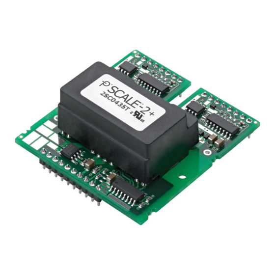
The new SCALE™-2+ dual-driver core 2SC0435T combines unrivalled compactness with broad applicability.
The driver was designed for universal applications requiring high reliability. The 2SC0435T drives all usual
high-power IGBT modules up to 1700V. The embedded paralleling capability allows easy inverter design
covering higher power ratings. Multi-level topologies are also supported.
The 2SC0435T is the most compact driver core in its power range available for industrial applications, with a
footprint of only 57.2mm x 51.6mm and an insertion height of max. 20.5mm. It allows even the most
restricted insertion spaces to be efficiently used.
Fig. 1 2SC0435T driver core
www.power.com/igbt-driver
Page 1
Advertisement
Table of Contents

Related Manuals for Power integrations Scale-2+ 2SC0435T

Summary of Contents for Power integrations Scale-2+ 2SC0435T
-
Page 1: Abstract
SCALE™-2+ 2SC0435T SCALE™-2+ 2SC0435T Preliminary Description & Application Manual Dual-Channel High-power IGBT Driver Abstract The new SCALE™-2+ dual-driver core 2SC0435T combines unrivalled compactness with broad applicability. The driver was designed for universal applications requiring high reliability. The 2SC0435T drives all usual high-power IGBT modules up to 1700V. -
Page 2: Table Of Contents
SCALE™-2+ 2SC0435T Preliminary Description & Application Manual Contents Abstract ............................1 Contents ............................2 Driver Overview ..........................4 Mechanical Dimensions ........................5 Pin Designation ..........................7 Recommended Interface Circuitry for the Primary Side Connector ..........8 Description of Primary Side Interface ................... 8 General .......................... - Page 3 SCALE™-2+ 2SC0435T Preliminary Description & Application Manual Technical Support ........................17 Quality ............................17 Legal Disclaimer ........................... 18 Ordering Information ........................19 Information about Other Products ....................19 Power Integrations Sales Offices ....................20 www.power.com/igbt-driver Page 3...
-
Page 4: Driver Overview
Preliminary Description & Application Manual Driver Overview The 2SC0435T is a driver core equipped with Power Integrations' latest SCALE-2+ chipset /1/. The SCALE-2+ chipset is a set of application-specific integrated circuits (ASICs) that cover the main range of functions needed to design intelligent gate drivers. The SCALE-2+ driver chipset is a further development of the proven SCALE technology /2/. -
Page 5: Mechanical Dimensions
SCALE™-2+ 2SC0435T Preliminary Description & Application Manual Mechanical Dimensions Fig. 3 Interactive 3D drawing of 2SC0435T2H0-17 www.power.com/igbt-driver Page 5... - Page 6 SCALE™-2+ 2SC0435T Preliminary Description & Application Manual X=2.54mm (100mil) for 2SC0435T2H0-17 and 2SC0435T2H0C-17 X=3.1mm (122mil) for 2SC0435T2G1-17 and 2SC0435T2G1C-17 X=5.84mm (230mil) for 2SC0435T2F1-17 and 2SC0435T2F1C-17 Fig. 4 Mechanical drawing of 2SC0435T The primary side and secondary side pin grid is 2.54mm (100mil) with a pin cross section of 0.64mm x 0.64mm.
-
Page 7: Pin Designation
SCALE™-2+ 2SC0435T Preliminary Description & Application Manual Pin Designation Pin No. and Name Function Primary Side DC/DC converter supply Status output channel 1; normally high-impedance, pulled down to low on fault Status output channel 2; normally high-impedance, pulled down to low on fault Mode selection (direct/half-bridge mode) Set blocking time Supply voltage;... -
Page 8: Recommended Interface Circuitry For The Primary Side Connector
SCALE™-2+ 2SC0435T Preliminary Description & Application Manual Recommended Interface Circuitry for the Primary Side Connector Fig. 5 Recommended user interface of 2SC0435T (primary side) Both ground pins must be connected together with low parasitic inductance. A common ground plane or wide tracks are strongly recommended. -
Page 9: Vdc Terminal
SCALE™-2+ 2SC0435T Preliminary Description & Application Manual VDC terminal The driver has one VDC terminal on the interface connector to supply the DC-DC converters for the secondary sides. VDC should be supplied with 15V. It is recommended to connect the VCC and VDC terminals to a common 15V power supply. -
Page 10: Ina, Inb (Channel Drive Inputs, E.g. Pwm)
Note that the dead time may vary from sample to sample. A tolerance of approximately ±20% may be expected. If higher timing precisions are required, Power Integrations recommends using the direct mode and generating the dead time externally (refer to the Application Note AN-1101 /4/). -
Page 11: Recommended Interface Circuitry For The Secondary Side Connectors
SCALE™-2+ 2SC0435T Preliminary Description & Application Manual Note: It is also possible to apply a stabilized voltage at TB. The following equation is used to calculate the voltage V between TB and GND in order to program the desired blocking time T (typical value): ... -
Page 12: Dc/Dc Output (Visox), Emitter (Vex) And Comx Terminals
(drain-source) voltage exceeds a predefined threshold. The power semiconductor is then kept in linear operation. Basic active clamping topologies implement a single feedback path from the IGBT’s collector through transient voltage suppressor devices (TVS) to the IGBT gate. The 2SC0435T supports Power Integrations' Advanced www.power.com/igbt-driver Page 12... -
Page 13: Gate Turn-On (Ghx) And Turn-Off (Glx) Terminals
SCALE™-2+ 2SC0435T Preliminary Description & Application Manual Active Clamping, where the feedback is also provided to the driver’s secondary side at pin ACLx: as soon as the voltage on the right side of the 20Ω resistor (Fig. 7) exceeds about 1.3V, the turn-off MOSFET is progressively switched off in order to improve the effectiveness of the active clamping and to reduce the losses in the TVS. -
Page 14: How Do 2Sc0435T Scale-2+ Drivers Work In Detail
SCALE™-2+ 2SC0435T Preliminary Description & Application Manual A resistor between GLx and COMx of 4.7kΩ (other values are also possible) may be used in order to provide a low-impedance path from the IGBT/MOSFET gate to the emitter/source even if the driver is not supplied with power. -
Page 15: Vce Monitoring / Short-Circuit Protection
SCALE™-2+ 2SC0435T Preliminary Description & Application Manual monitoring / short-circuit protection Each channel of the 2SC0435T driver is equipped with a V monitoring circuit. The recommended external circuitry is shown in Fig. 7. A resistor in Fig. 7) is used as the reference element for defining the turn-off threshold. -
Page 16: Desaturation Protection With Sense Diodes
SCALE™-2+ 2SC0435T Preliminary Description & Application Manual As the parasitic capacitances on the host PCB may influence the response time it is recommended to measure it in the final design. It is important to define a response time which is smaller than the max. allowed short- circuit duration of the used power semiconductor. -
Page 17: Bibliography
The Information Source: SCALE-2 and SCALE-2+ Driver Data Sheets Power Integrations offers the widest selection of gate drivers for power MOSFETs and IGBTs for almost any application requirements. The largest website on gate-drive circuitry anywhere contains all data sheets, application notes and manuals, technical information and support sections: www.power.com. -
Page 18: Legal Disclaimer
SCALE™-2+ 2SC0435T Preliminary Description & Application Manual Legal Disclaimer The statements, technical information and recommendations contained herein are believed to be accurate as of the date hereof. All parameters, numbers, values and other technical data included in the technical information were calculated and determined to our best knowledge in accordance with the relevant technical norms (if any). -
Page 19: Ordering Information
For other drivers, product documentation, evaluation systems and application support Please click onto: www.power.com 2009…2018 Power Integrations Switzerland GmbH. All rights reserved. We reserve the right to make any technical modifications without prior notice. Version 2.7 from 2018-02-05 www.power.com/igbt-driver... -
Page 20: Power Integrations Sales Offices
SCALE™-2+ 2SC0435T Preliminary Description & Application Manual Power Integrations Sales Offices WORLD HEADQUARTERS AMERICAS EAST AMERICAS CENTRAL 5245 Hellyer Avenue 7360 McGinnis Ferry Road 333 Sheridan Road San Jose, CA 95138 USA Suite 225 Winnetka, IL 60093 USA Tel: +1-408-414-9200...
Need help?
Do you have a question about the Scale-2+ 2SC0435T and is the answer not in the manual?
Questions and answers