
Related Manuals for Lockformer Vulcan 2900

Summary of Contents for Lockformer Vulcan 2900
- Page 1 H. WEISS MACHINERY & SUPPLY PHONE: (718) 605-0395 - www.hweiss.com 711 OGDEN AVE. LISLE IL. 60535-1399 PHONE 630-964-8000 FAX 630-964-5685 REV 08-98...
- Page 2 FROM THE SHIPPING SKIDS completely thread the adjustment nut as shown in the illustration, then fully thread a leveler into each leg. DO NOT ANCHOR THE TABLE TO THE FLOOR. A Lockformer installation technician will level the equipment and secure it to the floor.
- Page 3 H. WEISS MACHINERY & SUPPLY PHONE: (718) 605-0395 - www.hweiss.com SHIPPING BRACKET REMOVAL IMPORTANT! REMOVE THE STEEL ANGLE BRACKETS (YELLOW) SHOWN IN THE PHOTOS BELOW BEFORE ATTEMPTING TO OPERATE YOUR VULCAN MACHINE. THESE ITEMS WERE USED TO SECURE THE MACHINE DURING SHIPPING. REPLACE THE TWO SOCKET HEAD CAP SCREWS SECURING THE BRACKETS ON THE CARRIAGE WITH THE SHCS IN THE BAG ATTACHED TO THE TORCH HEAD (ALLEN WRENCH INCLUDED).
- Page 4 H. WEISS MACHINERY & SUPPLY PHONE: (718) 605-0395 - www.hweiss.com BRACKET REMOVAL CONT. REMOVE THESE YELLOW BRACKETS BEFORE REMOVING TABLE. THESE BRACKETS ARE FOUND ON BOTH SIDES OF THE VULCAN MACHINE.
- Page 5 H. WEISS MACHINERY & SUPPLY PHONE: (718) 605-0395 - www.hweiss.com BRACKET REMOVAL CONT. REMOVE THIS BRACKET BEFORE OPERATING THIS MACHINE WHEEL SIDE OF CARRIAGE SHIPPING BRACKET REMOVAL 1. Position an appropriate, safe jacking device and carefully lift the carriage enough to take the weight off of the yellow shipping bracket.
-
Page 6: Safety Information
H. WEISS MACHINERY & SUPPLY PHONE: (718) 605-0395 - www.hweiss.com SAFETY INFORMATION YOU ARE NOT READY TO OPERATE THIS EQUIPMENT IF YOU HAVE NOT READ AND UNDERSTOOD THE SAFETY INFORMATION IN THIS MANUAL. SAFETY FIRST! All Personnel working with or near the Vulcan must read this section! In addition to the following guidelines, refer to Sections 1, 2, and 3 of this manual for additional safety information. - Page 7 H. WEISS MACHINERY & SUPPLY PHONE: (718) 605-0395 - www.hweiss.com BURN SAFETY - Intense ultraviolet light, sparks, and hot metal produced by plasma arc cutting will harm either exposed skin or eyes. Operators and nearby personnel must wear protective clothing and equipment to avoid hazards.
- Page 8 H. WEISS MACHINERY & SUPPLY PHONE: (718) 605-0395 - www.hweiss.com Stock containing or coated with significant percentages of beryllium, cadmium, lead, mercury, or zinc can all give off poison fumes when burned by plasma arc cutting. Do not cut this stock unless the operator, or anyone else subjected to the fumes, wears respiratory equipment or an air supplied helmet, or the table ventilation system is working efficiently.
- Page 9 H. WEISS MACHINERY & SUPPLY PHONE: (718) 605-0395 - www.hweiss.com Before changing the torch parts, disconnect the main power or unplug the power supply. After changing the torch parts and returning the retaining cap to its operating position, plug the power supply in again.
- Page 10 H. WEISS MACHINERY & SUPPLY PHONE: (718) 605-0395 - www.hweiss.com Never use an oxygen hose for any gas other than oxygen. Use the shortest possible lengths of hose to avoid damage, reduce pressure drop, and prevent possible volume flow restriction. Let the hose lie as straight as possible to prevent kinks when interconnecting system components.
- Page 11 H. WEISS MACHINERY & SUPPLY PHONE: (718) 605-0395 - www.hweiss.com cable and the torch lead on one side of your body. Keep your body from coming in between the torch lead and the work cable. (2) Keep distance of work cable to workpiece as short as possible to eliminate loop areas.
- Page 12 H. WEISS MACHINERY & SUPPLY PHONE: (718) 605-0395 - www.hweiss.com PUBLICATION INDEX The Publication Index contains a list of publications dealing with plasma arc cutting equipment safety practices. American National Standards Institute, 1430 Broadway, New York, NY 10018 (212) 354-3300. ANSI Standard Z41.1, Standard for Men's Safety-Toe Footwear ANSI Standard Z49.2, Fire Prevention in the Use of Cutting and Welding Processes ANSI Standard Z88.2, Practices for Respiratory Protections...
- Page 13 H. WEISS MACHINERY & SUPPLY PHONE: (718) 605-0395 - www.hweiss.com THIS SAFETY ALERT SYMBOL INDICATED IMPORTANT SAFETY MESSAGES IN THIS MANUAL. WHEN YOU SEE THIS SYMBOL CAREFULLY READ THE MESSAGE THAT FOLLOWS AND BE ALERT TO THE POSSIBILITY OF PERSONAL INJURY OR DEATH. WARNING BEFORE ANY MACHINE IS USED BY AN EMPLOYEE OR IS LOANED OR RENTED, MAKE ABSOLUTELY CERTAIN THAT THE OPERATOR(S) PRIOR TO...
- Page 14 H. WEISS MACHINERY & SUPPLY PHONE: (718) 605-0395 - www.hweiss.com WARNING, DO NOT HANDLE MATERIAL (COIL, SHEET OR BLANK) WITHOUT WEARING PROTECTIVE GLOVES. WARNING, NARROW OR UNSTABLE COILS MUST NOT BE TRANSPORTED WITHOUT THE AID OF BLOCKING AND/OR SIDE SUPPORTS DANGER, COILS MUST NEVER BE CARRIED OVER THE HEADS OF OTHER EMPLOYEES.
- Page 15 H. WEISS MACHINERY & SUPPLY PHONE: (718) 605-0395 - www.hweiss.com WARNING, DO NOT OPERATE ANY EQUIPMENT WITHOUT GUARDS AND COVERS INSTALLED IN PLACE. WARNING, KEEP THE WORK AREA CLEAR OF OBSTRUCTIONS AND THE FLOOR CLEAN AND DRY. WARNING, NEVER USE STOOLS, BOXES, CRATES OR SIMILAR ITEMS AS SUBSTITUTES FOR WORK PLATFORMS, SCAFFOLDING OR LADDERS.
- Page 16 H. WEISS MACHINERY & SUPPLY PHONE: (718) 605-0395 - www.hweiss.com The Lockformer Company, 711 Ogden Ave., Lisle, Ill. 60532 (630) 964-8000 TABLE OF CONTENTS Reference Photo Section 1: Preliminary Machine Installation Safety Uncrating Location of Machine Checklist for Rail System...
- Page 17 H. WEISS MACHINERY & SUPPLY PHONE: (718) 605-0395 - www.hweiss.com Section 4: Lockformer Assembly Drawings And Parts Lists 51489 Y - Drive Motor Assembly 51491 Y - Two-Drive Motor Assembly 51494 X - Drive Motor Assembly 51495 X - Drive Motor Assembly 51526 Rail Assembly - 20 ft.
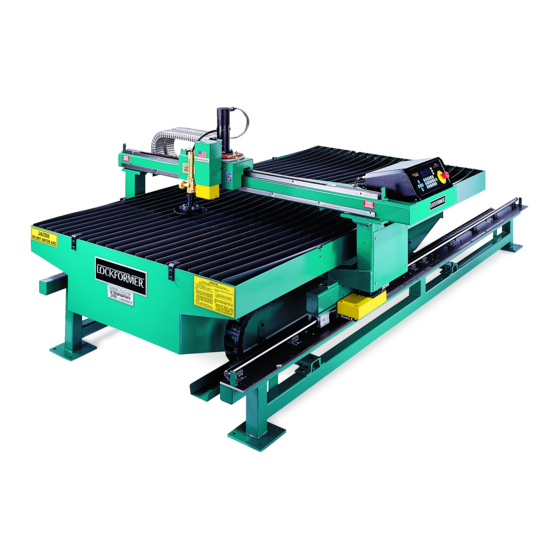
- Page 18 H. WEISS MACHINERY & SUPPLY PHONE: (718) 605-0395 - www.hweiss.com Vulcan 2900 REFERENCE PHOTO PNEUMATIC TORCH LIFTER "X" AXIS DRIVE MOTOR PLASMA TORCH CONTROLLER FLOATING HEAD "X" CARRIAGE "X" AXIS ("X" AXIS DRIVE) SUPPORT ROD "X" AXIS PRECISION BEARING RACK GEAR "X"...
- Page 19 H. WEISS MACHINERY & SUPPLY PHONE: (718) 605-0395 - www.hweiss.com SECTION 1 PRELIMINARY MACHINE INSTALLATION Safety Uncrating Location of Machine Checklist for Rail System Drive Rack Grounding Procedure / Power Supply Ventilation Fiber Optic Cable Reference...
- Page 20 H. WEISS MACHINERY & SUPPLY PHONE: (718) 605-0395 - www.hweiss.com Page 1 The following information outlines the factory procedures for preliminary installation of the Lockformer Vulcan Cutting Machine. Appropriate Lockformer reference and assembly drawings accompany this manual as section 4.
- Page 21 System’s ground wires by directing them all to same central tie point to an earth ground. Refer to accompanying Lockformer Assembly Drawings to assist in the correct arrangement of electrical connections for grounding. Figure # 1, which appears at the end of this section, is a Star Ground Assembly Drawing, showing suggested positioning for grounding wires.
- Page 22 H. WEISS MACHINERY & SUPPLY PHONE: (718) 605-0395 - www.hweiss.com Page 3 and any cable that must be the space where people walk. c. Connect the Star Ground to the ground rod with a stranded wire (minimum 2 AWG) This wire cannot be more than 4' long.
- Page 23 H. WEISS MACHINERY & SUPPLY PHONE: (718) 605-0395 - www.hweiss.com Page 4 INSTALLATION OF THE PROXIMITY SWITCH AND EMERGENCY PUSHBUTTON. Remove the bumper bracket and end cap from the carriage tubing. Remove the bag of components. Open the bag and remove its contents. Install the proximity switch back into the tubing and out through the mounting hole A .
- Page 24 H. WEISS MACHINERY & SUPPLY PHONE: (718) 605-0395 - www.hweiss.com EMERGENCY STOP CUTTING TABLE STAR GROUND POINT GROUND LOCKFORMER 5395 PLASMA ARC CONTROLLER POWER SUPPLY Figure 1...
- Page 25 H. WEISS MACHINERY & SUPPLY PHONE: (718) 605-0395 - www.hweiss.com SECTION 2 OPERATION AND PROCEDURES Loading the table with material Control Power-On Procedure Initial Torch/Head Set-Up Procedure Emergency Stop Plasma Unit Set-Up Job Download Exhaust Activation Dry Run Operation of Control During Cutting Releasing a Job to Start a New Job Lost Cut Recovery Vulcan Download Quick Chart...
- Page 26 SEE ILLUSTRATION #1 2. CONTROL POWER-UP PROCEDURE Turn the power on to the Lockformer 5395 controller using the main ON/OFF switch located at the rear. After the unit has completed the Power On Self Test (POST), release the Emergency stops;...
- Page 27 H. WEISS MACHINERY & SUPPLY PHONE: (718) 605-0395 - www.hweiss.com Page 2 3. INITIAL TORCH/HEAD SET-UP PROCEDURE The distance of the torch to the material is critical and must be checked prior to cutting the job and adjusted if necessary. The exact distance may vary according to material type and thickness. The Hypertherm operations manual provides the correct setting.
-
Page 28: Emergency Stop
The gas (air) supply should be clean, dry, and free of oil to ensure maximum consumable life. A three stage filter assembly is recommended to filter the gas (air). CONTACT LOCKFORMER SERVICE DEPARTMENT FOR DETAILS. Before applying power to the Plasma unit, verify that the input gas (air) pressure is set according to the figure as shown in the Hypertherm operations manual. - Page 29 6. JOB DOWNLOAD Lockformer 5395 Control Overview The display screen on the Lockformer 5395 control is a four line backlit graphics display and is used to present status and prompt information to the operator and at the same time provide soft key functionality with the keypad.
- Page 30 H. WEISS MACHINERY & SUPPLY PHONE: (718) 605-0395 - www.hweiss.com Page 5 Sp 300.0 To begin the dialog between the controller and the office Speed Kf 0.0 computer, press the CONTINUE key. Kerf Centre Continue The computer will respond by sending a request to the controller: To select a sheet from the Vulcan fittings program.
- Page 31 H. WEISS MACHINERY & SUPPLY PHONE: (718) 605-0395 - www.hweiss.com Page 6 8. DRY RUN Before cutting the first sheet, the operator may wish to Plasma perform a dry run of the sheet to check the torch cut path. selected To execute a dry run, press the DRY RUN key.
- Page 32 H. WEISS MACHINERY & SUPPLY PHONE: (718) 605-0395 - www.hweiss.com Page 7 After the first sheet is cut, the torch will park at the (0, 120) position. SEE ILLUSTRATION #1. If the Autoloading option is engaged in the Companel2 program, the next sheet of the job will be downloaded automatically when the bridge has reached the park position.
- Page 33 11. LOST CUT RECOVERY If the transferred arc loses contact with the workpiece, the plasma Unit will shut off the DC-power to the torch and remove the machine motion input to the Lockformer control, stopping machine motion. When this happens, a prompt message is displayed; "Lost...
- Page 34 H. WEISS MACHINERY & SUPPLY PHONE: (718) 605-0395 - www.hweiss.com 12. VULCAN DOWNLOAD QUICK CHART EXECUTE A SHEET METAL JOB EXECUTE A BLANK 1. Turn on all power 1. Turn on all power 2. Press the DRIVES ON key 2. Press the DRIVES ON key 3.
- Page 35 H. WEISS MACHINERY & SUPPLY PHONE: (718) 605-0395 - www.hweiss.com Page 10 13. MANUAL DATA INPUT (MDI) MDI - "GO TO" INSTRUCTIONS 1. Press the ESC key to reach primary screen 2. Press F3 - Execute 3. Press F2 - MDI 4.
- Page 36 H. WEISS MACHINERY & SUPPLY PHONE: (718) 605-0395 - www.hweiss.com Page 11 14. SHAPE LIBRARY Plasma Press the ESC key to reach the primary screen. Press F2 Download selected Shape Lib - Shape Lib Execute Sp 70.0 Speed Press F3 - Continue Kf 0.00 Kerf Centre...
- Page 37 H. WEISS MACHINERY & SUPPLY PHONE: (718) 605-0395 - www.hweiss.com 15. VULCAN OPERATION FLOW CHART Download Speed Kerf Continue Job loaded from PC using Dialog mode. When loading is complete: Go To Rip To Rip Cut Speed Pierce On Dry Run Speed Kerf Continue...
- Page 38 H. WEISS MACHINERY & SUPPLY PHONE: (718) 605-0395 - www.hweiss.com Misc Para General Arc on fb To corner Height Speed Chain Cut Def. TI1 Language Pierce Dl. Height Cut ON/OFF Voltage Retract d: Current Plasma Marker Machine Units Display Job Data Keyboard M/c Size Serial...
- Page 39 H. WEISS MACHINERY & SUPPLY PHONE: (718) 605-0395 - www.hweiss.com 0,120 POINT AMC4 CONTROLLER WORKPIECE STOPS WORKPIECE APPROX. TORCH SET-UP POINT 0,0 POINT (Home Position) ILLUSTRATION 1...
- Page 40 H. WEISS MACHINERY & SUPPLY PHONE: (718) 605-0395 - www.hweiss.com ILLUSTRATION 3...
- Page 41 H. WEISS MACHINERY & SUPPLY PHONE: (718) 605-0395 - www.hweiss.com SECTION 3 MAINTENANCE Safety Inspection and Upkeep Lubrication Reinstallation and Assembly of the Vulcan Torch Head Torch Height Adjustment...
- Page 42 H. WEISS MACHINERY & SUPPLY PHONE: (718) 605-0395 - www.hweiss.com Page 1 1. SAFETY - Shut Off main power disconnect to cut off power from Vulcan (including Plasma Unit) before attempting to work on electrical circuits or performing any cleaning of machine that involves reaching in between parts that can move! Do not touch electrically hot parts! Keep cables dry, free of oil and grease, and protected at all times from damage by hot metal and sparks.
- Page 43 H. WEISS MACHINERY & SUPPLY PHONE: (718) 605-0395 - www.hweiss.com Page 2 4. REINSTALLATION AND ASSEMBLY OF THE VULCAN TORCH HEAD Regular maintenance of the torch head includes resetting the torch height for the stock being cut, and cleaning; as described at the end of this section. If a torch head is ever to be removed and a new one installed, or if a torch head has to be reset, use the following procedures: Disconnect primary power leads and gas tanks before beginning actual removal of torch head from...
- Page 44 H. WEISS MACHINERY & SUPPLY PHONE: (718) 605-0395 - www.hweiss.com Page 3 PHOTO 2 PHOTO 3 PHOTO 4 2. Loosen the Head fastening screws as shown in Photos 2 and 3, and remove the lower Assembly from the Head as shown in Photo 4.
- Page 45 H. WEISS MACHINERY & SUPPLY PHONE: (718) 605-0395 - www.hweiss.com Page 4 THREADED COLLAR 3. Remove the torch assembly from the holder casting. Now remove the torch body by loosening the threaded collar. Unscrew housing to expose wires. 4. Use a 3/32" hex key to remove 3 socket head screws and carefully disconnect the two fittings as follows: a.
- Page 46 H. WEISS MACHINERY & SUPPLY PHONE: (718) 605-0395 - www.hweiss.com Page 5 POWERMAX 800 (SEE HYPERTHERM MANUAL) 5. Torch Height Adjustment - In case a Torch Assembly’s setting is ever disturbed and needs resetting, or if a new Torch Head must be installed, The Torch Head’s ball casters and Torch Nozzle must be set correctly in relation to each other and to the sheets the Torch will cut.
- Page 47 IMPORTANT! Beside the normal service required for the Plasma Cutting Torch in its Instructions, the ball casters of the Lockformer Torch Head must be cleaned after every three or four panels, to prevent dust buildup and resultant clogging. To clean the ball casters, raise the Torch to its maximum height and shut off machine power supply.
- Page 48 H. WEISS MACHINERY & SUPPLY PHONE: (718) 605-0395 - www.hweiss.com SECTION 4 ASSEMBLY DRAWINGS AND PARTS LIST Assembly Drawings 51489 Y - Drive Motor Assembly 51491 Y - Two-Drive Motor Assembly 51494 X - Drive Motor Assembly 51495 X - Drive Motor Assembly 51648 Rail Assembly 51526 Rail Assembly - 20 ft.
- Page 49 H. WEISS MACHINERY & SUPPLY PHONE: (718) 605-0395 - www.hweiss.com SECTION 5 FIBER OPTICS INFORMATION Specifications Input / Output Interface System Malfunction Isolation Normal Fiber Optic Operation Quick Test - Will Not Download Checking the Fiber Optic System Checking the Fiber Optic Cable Bit-Driver Sensitivity Adjustment Bypassing the Fiber Optic System Office Cable Pin Configuration...
-
Page 50: Specifications
H. WEISS MACHINERY & SUPPLY PHONE: (718) 605-0395 - www.hweiss.com Page 1 The S.I. Tech Model 2005 Asynchronous Optical Bit-Driver is a short haul limited distance “modem.” At the transmission end, the Unit accepts digital information via an RS-232 connector. It converts this data for transmission over a Duplex optical fiber transmission line. - Page 51 H. WEISS MACHINERY & SUPPLY PHONE: (718) 605-0395 - www.hweiss.com Page 2 requiring Clear to Send. Data Set Ready is a D.C. level indicator to the terminal that the local Bit-Driver has power applied. Signal Ground is the level to which all voltages for the RS-232 interface are referenced. Data Carrier Detect is a control signal from the Bit-Driver which indicates a signal is being received from the remote Bit-Driver.
- Page 52 H. WEISS MACHINERY & SUPPLY PHONE: (718) 605-0395 - www.hweiss.com Page 3 9. Reconnect the optical fibers to the Bit-Driver. 10. Repeat tests 1 to 9, as necessary, for the remote Bit-Driver. 11. If a defect is still not isolated, the F/O cable may be defective. Its continuity can be roughly checked by placing connector at one end near a 60 watt or larger light.
- Page 53 H. WEISS MACHINERY & SUPPLY PHONE: (718) 605-0395 - www.hweiss.com 4. Normal Fiber Optic Operation Office Bit Computer NEE Controller Driver Office RD TD Cable Fiber Optic Cable Always On Normal Operation 1) Press DOWNLOAD on Controller. 2) TD light on internal bit-driver flashes (transmits data to office bit-driver). 3) RD light on Office bit-driver flashes (receives data from internal bit-driver).
- Page 54 H. WEISS MACHINERY & SUPPLY PHONE: (718) 605-0395 - www.hweiss.com 6. CHECKING THE FIBER OPTIC SYSTEM DCD RD Office RD TD Cable Paper Clip NOTE: Following directions exactly is necessary to ensure accurate results. 1) Turn Controller OFF. 2) Remove cover from Controller by removing the 6 phillips and 4 Allen screws. It may be necessary to remove the bolts that hold the controller down.
- Page 55 H. WEISS MACHINERY & SUPPLY PHONE: (718) 605-0395 - www.hweiss.com 8. BIT-DRIVER SENSITIVITY ADJUSTMENT In order to adjust the bit-driver, you must remove the black metal cover, then connect the fiber optic cable in reverse of normal operations at one end only. ("Cable Setting" Illustration below) 1) Turn the blue sensitivity potentiometer counterclockwise until the RD diode on the front panel lights up.
- Page 56 H. WEISS MACHINERY & SUPPLY PHONE: (718) 605-0395 - www.hweiss.com SECTION 6 TROUBLESHOOTING X and Y Axis Movement Cutting Errors Torch Movement Computer Block Flash Program Instructions to Install New Table Set-Up Software Computer Set-Up Controller Configuration...
- Page 57 This Section was prepared to make it easier for operating personnel to solve such problems quickly, so it is not necessary to consult Lockformer in many cases. Caution Shut Off All Incoming Power To Check Any Electrical Components Before Servicing!
- Page 58 H. WEISS MACHINERY & SUPPLY PHONE: (718) 605-0395 - www.hweiss.com Torch Movement Machine moves rapidly when Auto Zeroing X- Check encoder cable. axis, followed by screen message: Axes: X Following Error Exceeded Torch will not raise or lower 1. Check for any binding at torch lifter with power off.
- Page 59 H. WEISS MACHINERY & SUPPLY PHONE: (718) 605-0395 - www.hweiss.com FLASH PROGRAM Instructions to Install New Table Set-Up Software 1. Double click on the left mouse button, OS/2 full screen, insert the disk labelled "Table Set-Up Diskette #1" into drive A and type A:INSTALL and press Enter. Wait for 60 seconds and the screen will change and follow instructions.
- Page 60 H. WEISS MACHINERY & SUPPLY PHONE: (718) 605-0395 - www.hweiss.com...
- Page 61 H. WEISS MACHINERY & SUPPLY PHONE: (718) 605-0395 - www.hweiss.com...
- Page 62 H. WEISS MACHINERY & SUPPLY PHONE: (718) 605-0395 - www.hweiss.com...
- Page 63 H. WEISS MACHINERY & SUPPLY PHONE: (718) 605-0395 - www.hweiss.com NEE CONTROLLER BACK PANEL LAYOUT SERIAL SAFETY CONTROL INPUTS / OUTPUTS ENCODERS 24 V. D.C. LIFTER MARKER MOTORS BATTERY HOLDER INTERNAL BIT DRIVER MAIN FUSE DRIVE FUSE MAIN MAIN GROUND ACCESS PLATE ON / OFF PLUG...
- Page 64 H. WEISS MACHINERY & SUPPLY PHONE: (718) 605-0395 - www.hweiss.com SECTION 7 ADDITIONAL INFORMATION...
- Page 65 PHONE: (718) 605-0395 - www.hweiss.com Foreword Foreword Preliminary Machine Preliminary Machine Installation Installation Operation and Operation and Procedures Procedures Lockformer Vulcan Lockformer Vulcan Maintenance Maintenance Assembly Drawings Assembly Drawings and Parts List and Parts List Fiber Optics Fiber Optics Information...
Need help?
Do you have a question about the Vulcan 2900 and is the answer not in the manual?
Questions and answers
How to change jog speed
To change the jog speed on the Lockformer Vulcan 2900, press the SPEED key on the front panel. The display will show the current preset speed and the override percentage. Use the F1 key to increase the speed by 3% and the F2 key to decrease it by 3%. For larger changes, repeat pressing the keys as needed.
This answer is automatically generated