Advertisement
Quick Links
I
SIGHT
n
FLEX-MOUNT
™
TRAILER BRAKE CONTROL
IMPORTANT
Read the following instructions carefully before installing
and/or operating the brake control.
INSTALLATION PRECAUTIONS
• Braking capacity is for 2, 4, 6 or 8 trailer brake applications.
• This brake control will apply the trailer brakes while in reverse.
• This brake control is inertia activated. When the vehicle is not
moving, the brake control will not automatically apply the trailer
brakes. In this event, the manual brake must be depressed to
actuate the brakes.
• This brake control is not reverse polarity protected. Reversing
the connection to the vehicle battery or the breakaway battery
on the trailer will damage the brake control.
• This brake control is designed to operate trailers with electric or
electric/hydraulic brakes.
• For best results when installing components with double sided
tape, make sure to prep the area by cleaning it with rubbing
alcohol first.
INSTALLATION GUIDE
• Smart-Box
Mounting:
™
Locate an area under the vehicle dash on center console
or kick panel to mount the Smart-Box, making sure it is not in
a position that interferes with the emergency brake or pedal
operation. Orientation of the Smart-Box Mount should be where
[SIDE A] of the Smart-Box mounts against the kick panel or
center console. Allow enough room to plug in the brake control
harness and peripheral devices easily. Mount with foam tape,
cable ties or self-tapping screws (provided).
KICK PANEL
CAUTION
DO NOT MOUNT ON DASH
ONLY MOUNT ON KICK PANEL OR CENTER CONSOLE
• Flex-Control
and Flex-Display
Mounting:
™
™
1. Sit in the driver's seat and decide where you want to install
the Flex-Display™ and Flex-Control™. Make sure that the
Flex-Display is within sight lines that will allow you
to locate it easily while driving. The Flex-Control should be
mounted in a position that it is within easy reach while
driving.
2. Once the installation locations are determined, bring the
Flex-Display™ to the area it will be mounted and begin to
run the wire either behind vehicle panels or behind weather
stripping down to the Smart-Box™. Use double sided tape
to secure the Flex-Display™ to desired mounting location.
Apply tape to the bottom of the display bracket, or remove
the display bracket and attach the tape directly to the back
of the display.
3. With the Flex-Control
in the desired location, run the wire to
™
the Smart-Box
using the vehicle's dash seams and panels to
™
conceal the wire. Use double-sided tape to secure the Flex-
Control
to desired mounting location.
™
[Optional: Use Control Bracket and attach to dash with screws
or double sided tape. Optional mounting bracket flexes to allow
easy mounting to curved surfaces.]
4. With all wires routed down to the Smart-Box
location, plug all
™
peripheral wires into the Smart-Box
.
™
™
FLEX-DISPLAY
FLEX-CONTROL
™
HOW TO ATTACH TO
VEHICLE FACTORY TOW PACKAGE
If your vehicle came equipped with a factory tow package, brake
control function wires may exist under the vehicle dash. Consult
vehicle manual or call for location. Purchase a vehicle specific
Plug-in Simple!
brake control connector and simply plug into
®
the factory tow package plug, or splice the wires to the function
wires under the dash.
Black wire – positive terminal (+) on battery
Red wire – cold side of stop lamp switch or brake light
White wire – ground/negative terminal (-) on battery
Blue wire – trailer electric brakes
CONTROL BRACKET
SMART-BOX
™
™
BRAKE CONTROL
BLACK
WIRE COLOR
MODEL
VEHICLE WIRE COLOR
MAKE
& YEAR
CHEVY
2007
LIGHT
(New
& GMC
RED
BLUE &
- 2013
Style)
WHITE
CHEVY
1999 - 2007
LIGHT
RED
& GMC
(Classic Style)
BLUE
DODGE 2009-2012
RED &
WHITE &
YELLOW
VIOLET
DODGE 2003-2008
RED &
BLUE &
WHITE
WHITE
DODGE 1997-2002
RED
WHITE
FORD F-250 / 350
RED &
BLUE
2009-2013
BROWN
ORANGE
FORD F-150 2009-
RED OR
GREEN
RED &
OR YEL
2013
GRAY
FORD
F-150
LIGHT
RED
1994-2008
GREEN
TOYOTA
2003-2012
GREEN &
BLACK
LEXUS
YELLOW
&
VEHICLE MANUFACTURER
WIRING CODES
For installations on vehicles WITHOUT a factory
tow package use the following procedure:
1. Be sure to use proper wire gauge when installing your control
(12 gauge for electric brakes and positive power, 16 gauge for
the stop lamp switch and ground).
2. Connect the white wire directly to the negative post on the
vehicle battery. Grounding to any other location may cause
intermittent brake control operation or failure.
3. Attach 20-amp circuit breaker (for 6 or 8 brake use 30-amp)
or in-line fuse to the positive terminal on the vehicle's battery.
Route black wire from the brake control to the fuse or breaker.
4. Splice the red wire into the cold side of the vehicle's stop lamp
switch located by the brake pedal. Find the wire by using a
circuit tester and probing for the wire that powers the vehicle
stop lamps when the brake pedal is pressed.
5. Route the blue wire from the brake control to the vehicle side
towing connector at the rear of the tow vehicle.
NOTES
• Some late model Ford/Mercury trucks and sport utility vehicles
have 2 or more stop lamp switch wires. For proper operation,
use the light green wire. The other wire is red with a green
stripe. This wire goes directly to ground when not in use.
Splicing into this wire will short circuit your brake control and
possibly damage the unit.
• For Chevrolet vehicles 1999-06, if your vehicle does not have
a towing package, only the ground and stop lamp switch will be
active in the function wires under the dash. The electric brake
wire and 12-volt power lead will be terminated outside the
firewall. These will have to be routed to the trailer connector and
battery on the vehicle.
• For Chevrolet vehicles 2007 New Body Style-13, only the
ground and stop lamp switch will be active in the function wires
under the dash. The electric brake wire and 12-volt power lead
will be terminated outside the firewall. These will have to be
routed to the fuse block on the vehicle. 20-amp fuses will need
to be installed to power these functions.
• For Dodge 2005-06, to find the cold side of the stop lamp
switch, you must have the key in the "on" position.
• Ford and Dodge tow packages come with a 20-amp battery
feed wire system that will accommodate 2 and 4 brake trailer
magnets. An upgrade to a 30-amp (12 gauge) battery wire
system will be needed for 6 brake systems.
(optional)
OPERATING AND SETTING
RED
WHITE
BLUE
YOUR CONTROLLER
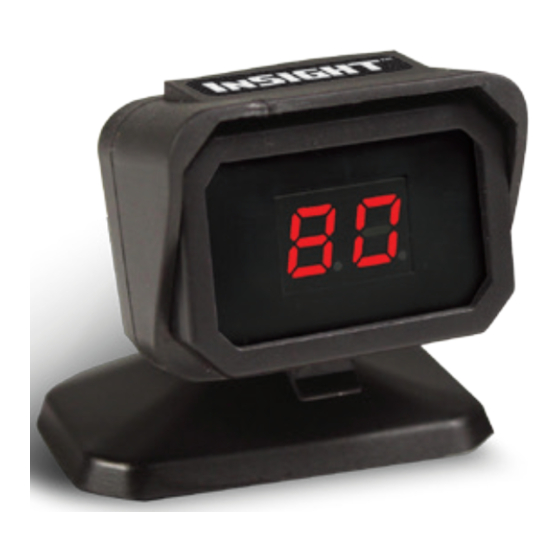
1. RED DOT
A red dot on bottom-right hand corner of the
DARK
digital display indicates trailer is connected.
WHITE
BLUE
DARK
BLACK
2. BLANK
BLUE
A blank display (no dot) indicates trailer is not
BLACK &
DARK
connected.
DRK GREEN
GREEN
(blank)
BLACK &
BLUE
GREEN
3. POWER
BLACK
BLUE
Power adjustment buttons (+/-) on top of the
BLACK &
control adjust power sent to the trailer brakes.
BLUE
GRAY
Pressing the (-) button decreases power.
Pressing (+) increases power. Power will be
WHITE &
displayed as a percentage on the digital display
BLUE
BROWN
GRN
from 5 to 99 in increments of 5%.
DARK
WHITE
4. SENSITIVITY
BLUE
This feature makes your trailer braking
BLACK &
BLUE &
response more or less sensitive. A setting of 1
WHITE
RED
indicates least sensitive. A setting of 7 indicates
most sensitive. Adjust the sensitivity by pressing
the button labeled "S" on the side of the unit.
5. SHORT CIRCUIT
SC indicates that a short circuit has occurred
TESTING / ADJUSTING
THE BRAKING RESPONSE:
Connect to your trailer and test drive on a dry open area at low
speed (20 to 25 mph). Apply vehicle brakes aggressively.
1. If trailer brakes lock-up, adjust down the power setting to just
below brake lock-up by pressing the (-) power button.
2. If the braking performance from the trailer feels as if it is
pushing the tow vehicle, adjust the power setting higher by
pressing the (+) power button. Repeat process until smooth
braking is obtained.
Discover various trailer hitches and towing in our online store.
Advertisement

Need help?
Do you have a question about the InSIGHT and is the answer not in the manual?
Questions and answers