Table of Contents
Advertisement
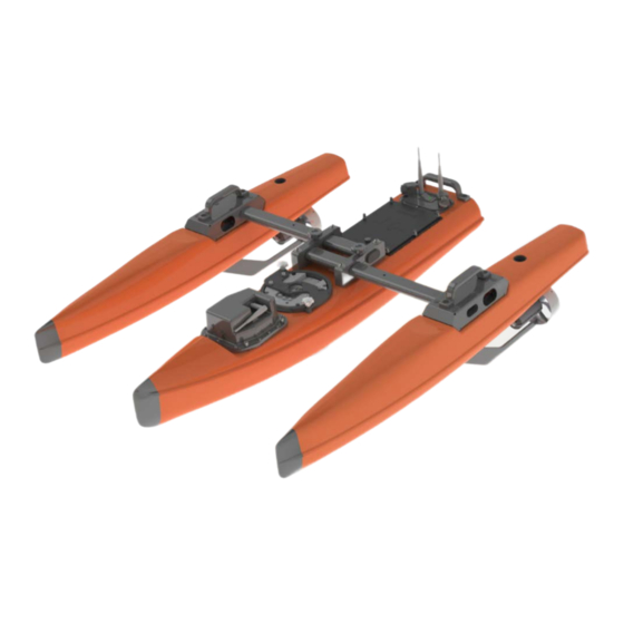
Q-1250
Z-1250
Power Trimaran
User's Guide
Information included herein is controlled by the Export Administration Regulations (EAR) and may
require an export license, license exception or other approval from the appropriate U.S. Government
agency before being exported from the United States or provided to any foreign person. Diversion
contrary to U.S. law is prohibited.
P/N 95L-8001-00 (September 2017)
© 2017 Teledyne Oceanscience, Inc. All rights reserved.
Advertisement
Table of Contents

Need help?
Do you have a question about the Q-1250 and is the answer not in the manual?
Questions and answers