Table of Contents
Advertisement
Advertisement
Table of Contents

Subscribe to Our Youtube Channel
Related Manuals for Valsi G80MG1500KVAE

Summary of Contents for Valsi G80MG1500KVAE
-
Page 2: General Description
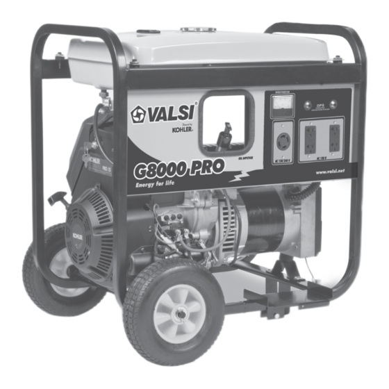
SPECIFICATIONS G80MG1500KVAE GENERAl dESCRIPTION FEATURES OIl SENSOR Oil sensor automatically shuts off the engine whenever Start Switch the oil level falls down below the lower limit to protect the engine from seizure. NO RADIO NOISE Air filter Noise suppressor spark plug is equipped to prevent radio frequency interference. -
Page 3: No - Fuse Breaker
CONSTRUCTION SE100FX SPARE PARTS lIST NOTE: Some parts are shown for illustration purposes only and are not available individually as replacement parts. NOTE: only a licensed electrician should perform electrical repairs on this generator. NO - FUSE BREAKER: The no- fuse breaker protects the generator from getting damage by overloading or short circuit in the appliance. -
Page 4: Receptacle And Ac Plug
RECEPTAClE ANd AC PlUG These are used for taking AC output power from the generator. A total of two kinds of receptacles, each varying in rated voltage and current from another, are used. Each model has at least one receptacle to deliver the rated generator output. The number of AC plugs that can be connected are as many as the receptacles. - Page 5 BlOCK dIAGRAM OF THE CIRCUIT JUdGEMENT OF OIl lEVEl STOPPING CIRCUIT When sufficient oil is in the crankcase, both of inner and This automatically stops the engine running. outer electrodes are immersed in the oil through which current flows across the electrodes. The sensor judges CAUTIONS TO BE TAKEN ON that oil in the crankcase is sufficient.
-
Page 6: Safety Precautions
SAFETY PRECAUTIONS Use extreme caution near fuel. A constant danger of do not operate with wet hands or in the rain. explosion of fire exist. Severe electric shock may occur. If the generator is Do not fill fuel tank while the engine is running. Do not wet by rain or snow, wipe it and thoroughly dry it before smoke or use open flame near the fuel tank. -
Page 7: Measuring Procedures
Efficiencies of some electrical appliances are as MEASURING PROCEdURES follows: Single-phase motor 0.6 to 0.75 MEASURING INSTRUMENTS Fluorescent lamp 0.7 to 0.8 (The smaller the motor, the lower the efficiency) VOlTMETER Example 1: A 40W fluorescent lamp means that AC voltmeter is necessary. its luminous output is 40W. -
Page 8: Ac Output Measuring
STATOR TACHOMETER Measure the insulation Use the contactless type resistance between tachometer each lead wire and the core. AC OUTPUT MEASURING ROTOR Measure the insulation resistance between the slip ring and the core. Use a circuit above for measuring AC output. CONTROl PANEl A hot plate or lamp with a power factor of 1.0 may be used Measure the insulation... -
Page 9: Disassembly And Assembly
STATOR Disengage connectors on the wires from stator and check the resistance between wires with a circuit tester referring to the table below. NOTE : If the circuit tester is not sufficiently accurate, it may not show the values given and may give erroneous readings. Erroneous readings will also occur when there is a wide 2.2 Pull out the gasoline 2.3 Lift and remove the... -
Page 10: Alternator Disassembly
3.3 Separate the control panel cable housing from alternator wire housing and remove 4 .2 each one of the cables from the receptacle housing. Do this carefully using a very small flat screwdriver. Finally, unscrew the control panel ground terminal using (Phillips) screwdriver. - Page 11 5.3 Use a big flat screwdriver to place it between the rotor and stator to avoid rotation of the rotor so that the nut (using a 1/2” wrench) from the alternator stud bolt pin. 5.6 Use a 9/16” wrench to unscrew the four bolts that hold the alternator flange to the engine and then remove the flange.
-
Page 12: Installation
Fasten the complete alternator to the flange using the PRElIMINARYCHECKS 4 screws V1 and washers R1 provided (driving torque On receipt it is recommended to inspect the alternator 25Nm). (fig. 1B). to find out whether it has got damages during Lock axially the rotor by placing the washer R2 and transportation. - Page 13 G80 GENERAl dRAWING ASSEMBlY SPECIFICATIONS SUBJECT TO CHANGE WITHOUT NOTICE...
- Page 14 G80 GENERATOR ElECTRICAl WIRING dIAGRAM SPECIFICATIONS SUBJECT TO CHANGE WITHOUT NOTICE...
- Page 15 SPECIFICATIONS SUBJECT TO CHANGE WITHOUT NOTICE...
- Page 16 Imported by: Nationwide Service Centers Guadalajara Headquarter Phone. 52 (33) 3668•2560 Fax 52 (33) 3668•2557 e-mail: valsiexport@gmail.com www.valsi.net Call: 888-ready-19 (888-73239-19) SPECIFICATIONS SUBJECT TO CHANGE WITHOUT NOTICE...
Need help?
Do you have a question about the G80MG1500KVAE and is the answer not in the manual?
Questions and answers