Table of Contents
Advertisement
Quick Links
SYSTEMS, Inc.
INSTALLATION
INSTRUCTIONS
FG-1025Z
Model
Glass-Break Detector
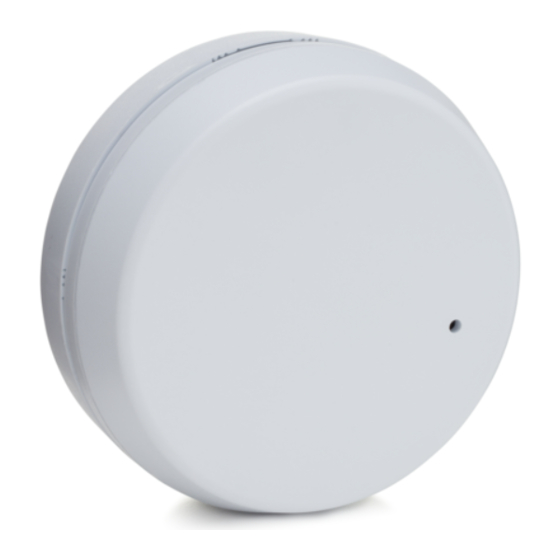
PRODUCT DESCRIPTION
The FG-1025Z is a directional glass-break detector. Two
microphones and time-of-arrival processing allow the unit to
provide precisely-defined protected and excluded zones.
For a detailed description of how the FG-1025Z works, refer to
the Technical Information section on page 5.
WIRING
1. For surface-wired installation, use optional Wiring Spacer
Plate (model number FG-SP2).
2. Route wire through Wire Entry Hole in the center of the
printed circuit board (PCB), and strip wire ends 1/4" (6.5 mm).
3. Wire the unit as shown, (use 22 - 18 AWG). Reverse polarity
connections will not damage the unit.
4. When wiring is complete, push excess wire back into the
ceiling. (Refer to the Mounting Locations section.)
NOTE: If end-of-line resistors are required, wire as shown in Figures
2c and 2d.
Front Microphone
Figure 1
Power
25 mA at
12 VDC
LEDs
Alarm
Form C
125 mA max
25 VDC max
Figure 2
WIRING
Command Input
Active low (0-1.5V);
or Remote LED
Select function
at S2-3
Terminal
Blocks
Wire
Entry
Hole
DIP Switch
Back
Microphone
Figure 2a
Wiring for a
N.C. loop, no
EOL resistor
FEATURES
•
Advanced microcontroller
with Digital Signal Process-
ing (DSP)
•
Precise 160
o
160
excluded zones
•
Dual microphones with
time-of-arrival (TOA)
processing
•
Continuous self-test
•
No adjustments
•
No minimum range
•
Remote Test Mode activation
with FG-701 simulator
•
End-of-line / spare terminals
WIRING
(Continued)
Keepout
Zones
Trouble
Output
Open
collector
MOUNTING LOCATION
1K series
resistor
For the greatest flexibility in aiming the FG-1025Z, mount the unit
on the ceiling. Figure 3 illustrates the protected, excluded and
keepout zones for a ceiling mounted FG-1025Z.
Tamper
25 mA max
The arrows printed on the intermediate cover (see Figure 1)
24 VDC max
indicate the direction of the protected zone. Refer to the
Mounting Guidelines to select an appropriate location, and refer
to the Aiming Guidelines to aim the unit properly. (
mounting is not possible, the unit can be mounted on a wall or post.)
- 1 -
•
Cover and wall tamper
•
Selectable Alarm Memory
•
LED enable
•
o
8 - 14 VDC operation
protected and
•
Energized Form C relay
•
PCB and housing designed
to protect against ESD and
mechanical damage
•
Watchdog for microcontroller
•
Green event LED lights when
sounds are processed
•
Dedicated trouble output
•
Selectable Command Input
or Remote LED Enable
Figure 2b
Wiring for a
N.O. loop, no
EOL resistor
Figure 2c
Wiring for a
N.C. loop with
EOL resistor
Figure 2d
Wiring for a
N.O. loop with
EOL resistor
If ceiling
Advertisement
Table of Contents

Subscribe to Our Youtube Channel
Related Manuals for C&K systems FG-1025Z


Summary of Contents for C&K systems FG-1025Z
- Page 1 Figure 2b For a detailed description of how the FG-1025Z works, refer to Wiring for a N.O. loop, no the Technical Information section on page 5.
- Page 2 PCB. DO NOT remove the PCB from the protective enclosure. Keepout Zone 20 Keepout Zone 2. For mounting the FG-1025Z sensor, #6 (M 3.5) or #8 (M 4) screws are recommended. (Screws are not provided.) EXCLUDED 3. If surface wiring is required, use the optional Wiring Spacer...
- Page 3 TEMPered glass sound. Other glass-break simulators will not OFF. give accurate indication of range. Note: If not used, you can leave the input unconnected. You must place the FG-1025Z in Test Mode before you can test the unit. Figure 7 Command/Remote...
- Page 4 S3 on the PCB (see Figure 1). This will activate Test Trouble detected Flash ON/OFF Flash OFF/ON Mode. Make sure to replace the front cover of the FG-1025Z Test mode, no alarm Flash once per second OFF before beginning test.
- Page 5 5 seconds (unaffected by TECHNICAL INFORMATION Discharges of either polarity to alarm LED latching) exposed surfaces The FG-1025Z is a directional glass-break detector. It has Tamper Switch: Dimensions: precisely-defined protected and excluded zones. There is no Combination cover and 4.25" OD x 0.88" THK...
- Page 6 LIMITED WARRANTY Seller warrants its products to be in conformance with its own plans and specifications and to be Seller does not represent that its product may not be compromised or circumvented; that the free from defects in materials and workmanship under normal use and service for 18 months from product will prevent any personal injury or property loss by burglary, robbery, fire or otherwise;...
Need help?
Do you have a question about the FG-1025Z and is the answer not in the manual?
Questions and answers