
Subscribe to Our Youtube Channel
Related Manuals for NAiS FP Series


Summary of Contents for NAiS FP Series
- Page 1 Programmable Controller FP0 RTD Unit Technical Manual is a global brand name of Matsushita Electric Works.
-
Page 2: Before Beginning
BEFORE BEGINNING Liability and Copyright for the Hardware This manual and everything described in it are copyrighted. You may not copy this manual, in whole or part, without written consent of Matsushita Electric Works (Europe) AG. Matsushita Electric Works (Europe) AG pursues a policy of continuous improvement of the design and performance of its products, therefore, we reserve the right to change the manual/product without notice. -
Page 3: Important Symbols
Important Symbols One or more of the following symbols may be used in this manual: WARNING The warning triangle indicates especially important safety instructions. If they are not adhered to, the results could be: • fatal or critical injury and/or •... - Page 4 CAUTION Indicates that you should proceed with caution. KEY POINTS Summarizes key points in a concise manner. SHORTCUTS Provides helpful keyboard shortcuts. EXPLANATION Provides brief explanation of a function, e.g. why or when you should use it.
-
Page 6: Table Of Contents
FP0 RTD Unit Table of Contents Table of Contents BEFORE BEGINNING ..................i LIMITED WARRANTY ..................i Important Symbols ..................ii Precautions Before Use ................vii Unit Outline.....................1 Functions ........................ 1 Product Number ..................... 1 Expansion Limit ...................... 1 Part Names and Functions..................2 Input Range Setting Switch..............4 Wiring......................5 Conversion Characteristics ..............6... - Page 7 FP0 RTD Unit Table of Contents When an Error Occurs .................20 Troubleshooting....................20 Digital Value When Out Of Measuring Range............20 Specifications..................21 Dimensions...................24 Index ......................25 Record of Changes..................27...
-
Page 8: Precautions Before Use
FP0 RTD Unitnit Precautions Before Use Precautions Before Use Accuracy When extremely sensitive temperature data is required, use the temperature data obtained 15 minutes after turning ON the FP0 RTD unit. (The temperature data obtained in the first 15 minutes is, however, within the total accuracy range.) A rapid temperature change in the FP0 RTD unit might change the temperature data temporarily. -
Page 10: Unit Outline
Unit Outline FP0 RTD Unit 1 Unit Outline 1.1 Functions RTD input unit for the FP0/FPΣ control unit. The temperature data obtained using the RTD (Resistance Temperature Detector) is converted to the digital value to be read into the FP0/ FPΣ control unit. Available RTD types Pt100 (to IEC751), Pt1000 (to IEC751), Ni1000 (to DIN43760), and Resistor. -
Page 11: Part Names And Functions
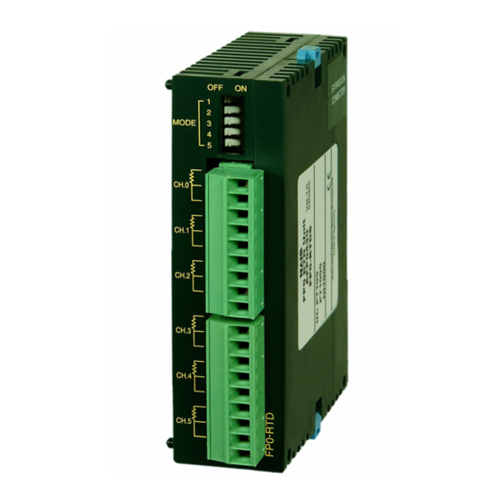
FP0 RTD Unit Unit Outline REFERENCE For further information, see page 14, I/O Allocation and Sample Programs. 1.4 Part Names and Functions Front Left side 1. Input range setting switch DIP switches to change between the input ranges (RTD types). REFERENCE For further information, see page 4, Input Range Setting Switch 2. - Page 12 Unit Outline FP0 RTD Unit 3. Expansion connector Connects the expansion unit to the internal circuit of the control unit. REFERENCE FP0 Hardware Manual: “Expansion I/O Units” FP∑User’s Manual: “Expansion” 4. DIN rail attachment lever (one-touch hook) The unit can be installed to the DIN rail by one-touch operation. The one-touch hook is also used for installing the unit to the FP0 Slim Type Mounting Plate (AFP0803).
-
Page 13: Input Range Setting Switch
FP0 RTD Unit Input Range Setting Switch 2 Input Range Setting Switch Input range setting switch MODE NOTE The following switch settings are read once when the control unit is turned ON. Changes will not be reflected if they are performed while the control unit is turned ON. -
Page 14: Wiring
Wiring FP0 RTD Unit 3 Wiring Wiring method Input line wiring NOTE Keep a distance of more than 100mm between the input line and the power line/high-voltage line. -
Page 15: Conversion Characteristics
FP0 RTD Unit Conversion Characteristics 4 Conversion Characteristics NOTE The measurement range available for degrees Celsius is larger than for degrees Fahrenheit as the digital value (temperature value displayed) for °F is higher than the one for °C. 4.1 Pt100 Input range:-200.0°C to 500.0°C/-328.0°F to 800.0°F, resolution: 0.1K/0.1°F Input value Input value... - Page 16 Conversion Characteristics FP0 RTD Unit Input range:-80.00°C to 80.00°C/-80.00°F to 80.00°F, resolution: 0.01K/0.01°F Input value Correspondence table for A/D conversion values Analog input Digital output Analog input Digital output value (°C) value value (°F) value -80.00 -8000 -80.00 -8000 +80.00 +8000 +80.00 +8000...
-
Page 17: Pt1000
FP0 RTD Unit Conversion Characteristics 4.2 Pt1000 Input range: -200.0°C to 300.0°C/-328.0°F to 572.0°F, resolution: 0.1K/0.1°F Input value Input value Correspondence table for A/D conversion values Analog input Digital output Analog input Digital output value (°C) value value (°F) value -200.0 -2000 -328.0... - Page 18 Conversion Characteristics FP0 RTD Unit Input range: -80.00°C to 80.00°C/-80.00°F to 80.00°F, resolution: 0.01K/0.01°F Input value Correspondence table for A/D conversion values Analog input Digital output Analog input Digital output value (°C) value value (°F) value -80.00 -8000 -80.00 -8000 +80.00 +8000 +80.00...
-
Page 19: Ni1000
FP0 RTD Unit Conversion Characteristics 4.3 Ni1000 Input range: -30.0°C to 150.0°C/-22.0°F to 302.0°F), resolution: 0.1K/0.1°F Input value Input value Correspondence table for A/D conversion values Analog input Digital output Analog input Digital output value (°C) value value (°F) value -30.0 -300 -22.0... - Page 20 Conversion Characteristics FP0 RTD Unit Input range: -30.00°C to 80.00°C/-22.00°F to 80.00°F, resolution: 0.01K/0.01°F Input value Input value Correspondence table for A/D conversion values Analog input Digital output Analog input Digital output value (°C) value value (°F) value -30.00 -3000 -22.00 -2200 +80.00...
-
Page 21: Resistor
FP0 RTD Unit Conversion Characteristics 4.4 Resistor Input range: 20Ω to 2200Ω, resolution: 1Ω (Ω) Input value Correspondence table for A/D conversion values Analog input Digital output value value (Ω) +2200 +2200 Processing if the input value range is exceeded Analog input Digital output value... - Page 22 Conversion Characteristics FP0 RTD Unit Input range: 20.0Ω to 163.0Ω, resolution: 0.1Ω (Ω) Input value Correspondence table for A/D conversion values Analog input Digital output value value (Ω) +20.0 +200 +1630.0 +16300 Processing if the input value range is exceeded Analog input Digital output value...
-
Page 23: O Allocation And Sample Programs
FP0 RTD Unit I/O Allocation and Sample Programs 5 I/O Allocation and Sample Programs 5.1 I/O Numbers Up to three expansion units including the FP0 RTD unit can be connected to the CPU (2 words [2x16 bits] are assigned to each WX and WY). I/O Numbers FP0/FPΣ... - Page 24 I/O Allocation and Sample Programs FP0 RTD Unit EXAMPLE The converted digital data is assigned to WX2 and WX3 when the FP0 RTD unit is installed as expansion unit no. 1. Converted data for CH1, 3, and 5 Converted data for CH0, 2, and 4 (signed 14-bit data) (signed 16-bit data) Conversion data switch flag...
-
Page 25: Programming With Fpwin Pro
FP0 RTD Unit I/O Allocation and Sample Programs 5.2 Programming with FPWIN Pro Control FPWIN Pro provides the convenient function block “Read_RTD6” to read data from the input channels. It can be used by the FP0 RTD unit for all RTD types (Pt100, Pt1000, Ni1000, and Resistor). -
Page 26: Programming With Fpwin Gr
I/O Allocation and Sample Programs FP0 RTD Unit 5.3 Programming with FPWIN GR 5.3.1 RTD Types Pt100, Pt1000, Ni1000 Ladder program to read data from input channels This program shows you how to store temperature data for CH0 to CH5 of the FP0 RTD unit installed as expansion unit no.1 in data registers DT0 to DT5. -
Page 27: Rtd Type Resistor
FP0 RTD Unit I/O Allocation and Sample Programs Data for CH3 Data after masking → 0100000000000001 → 0000000000000001 0111111111111111 → 1111111111111111 Bit D: recognizes positive or negative Conversion data switch flag NOTE X3D, X3E, X3F, WX2 and WX3 may be different, depending on where the FP0 RTD unit is installed. - Page 28 I/O Allocation and Sample Programs FP0 RTD Unit Conversion data switch flag When transferring the data from the FP0 RTD unit to the control unit, it is converted to 32-bit data including the channel information. Data for WX2 can be used as is, but the following procedure is required for WX3 data since its higher 2 bits are used as a conversion data switch flag.
-
Page 29: When An Error Occurs
FP0 RTD Unit When an Error Occurs 6 When an Error Occurs 6.1 Troubleshooting PROCEDURE 1. Check whether the input signal lines are connected properly. When the RTD is not connected properly or broken, K8191 is displayed for RTD types Pt100, Pt1000, and Ni1000. K16383 is displayed for the RTD type Resistor. 2. -
Page 30: Specifications
Specifications FP0 RTD Unit 7 Specifications General specifications Parameter Specifications Increase of current 25mA or less (24V DC) consumption in control unit Operating 0°C to +55°C temperature Storage -20°C to +70°C temperature Operating humidity 30%RH to 85%RH (no condensing) Storage humidity 30%RH to 85%RH (no condensing) Vibration 10Hz to 55Hz, 1 cycle/min: double amplitude of 75mm for 10 min. - Page 31 FP0 RTD Unit Specifications Parameter Specification Digital output -200.0 to 500.0°C: -2000 to 5000 Resolution 0.1 -328.0 to 800.0°F: -3280 to 8000 Pt100 -80.00 to 80.00°C: -8000 to 8000 Resolution 0.01 -80.00 to 80.00°F: -8000 to 8000 -200.0 to 300.0°C: -2000 to 3000 Resolution 0.1 -328.0 to 572.0°F:...
- Page 32 Specifications FP0 RTD Unit 3. Until conversion data is ready after the initial startup, the digital value shows 8191 or 16383. These are not temperature data. Program in such a way that these values are not interpreted as temperature data. 4.
-
Page 33: Dimensions
FP0 RTD Unit Dimensions 8 Dimensions... -
Page 34: Index
Index FP0 RTD Unit Index Input channels ........14, 21 Input range..........21 Input range setting switch.....2, 4 A/D conversion values ..See Conversion Input/output points ........22 characteristics Insulation method ........22 Accuracy ........... vii, 22 Addresses..........14 Masking ..........18 Measurement ranges........1 Block diagram .........23 Mode switch..........4 Broken-RTD detector......1, 23 Ni1000... - Page 35 FP0 RTD Unit Index Sampling cycle........22 Vibration resistance ........21 Shock resistance ........21 Specifications..........21 Storage humidity........21 Weight.............21 Storage temperature.......21 Wires............2 Wiring............5 Troubleshooting ........20...
-
Page 36: Record Of Changes
Record of Changes Manual No. Date Description of Changes ACGM0159V10END SEPT. 2004 First Edition... - Page 37 GLOBAL NETWORK North America Europe Asia Pacific China Japan Aromat Matsushita Matsushita Matsushita Matsushita Corporation Electric Works Electric Works Electric Works Electric Works Ltd. Automation Controls Group Europe H Europe Matsushita Electric Works (Europe) AG Rudolf–Diesel–Ring 2, D–83607 Holzkirchen, Tel. (08024) 648–0, Fax (08024) 648–111, www.mew–europe.com H Austria Matsushita Electric Works Austria GmbH Josef Madersperger Straße 2, A-2362 Biedermannsdorf, Austria, Tel.
Need help?
Do you have a question about the FP Series and is the answer not in the manual?
Questions and answers