
Related Manuals for ABATEC WAVE.COM4

Summary of Contents for ABATEC WAVE.COM4
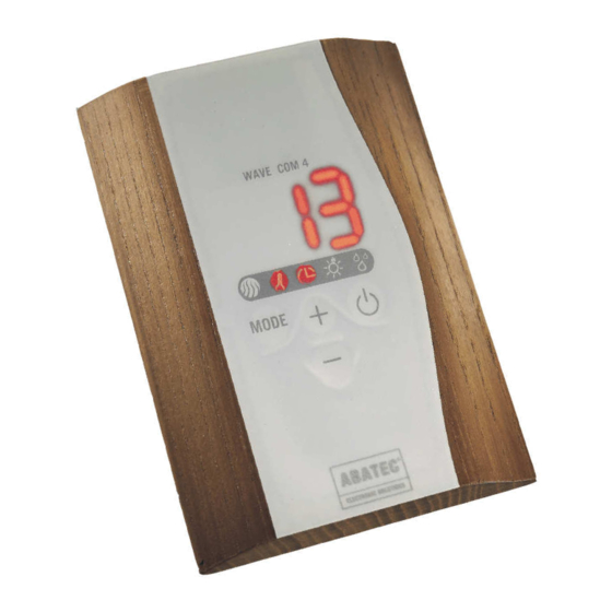
- Page 1 SAUNA CONTROL UNIT INSTRUCTION MANUAL The first unique patented modular high- end sauna control unit easily operated from both outside and inside the sauna cabin.
-
Page 3: Table Of Contents
page 1 of 32 INSTRUCTION MANUAL TABLE OF CONTENTS 1.0.0 UNIT DESCRIPTION 3.0.0 OVERVIEW OF THE COLOUR FUNCTIONS 1.1.0 GENERAL 1.2.0 OPERATIONAL MODE 3.1.0 COLOUR CODING 1.3.0 SCOPE OF APPLICATION 3.2.0 COLOUR SWITCH-ON 1.4.0 OVERVIEW/CLEANING 3.3.0 COLOUR AUTOMATIC MODE 1.5.0 STANDARD ACCESSORIES 3.4.0 COLOUR AUTOMATIC TIME... - Page 4 page 2 of 32 INSTRUCTION MANUAL 6.0.0 ELECTRICAL CONNECTIONS 6.1.0 TERMINAL OVERVIEW 6.2.0 OVERVIEW OF CABLE FEEDTHROUGH 6.3.0 OVERVIEW OF THE POWER UNIT 6.4.0 CONNECTIONS OF THE BASIC MODULE (ASBA) 6.4.1 DATA CABLE 6.4.2 TEMPERATURE SENSOR AND THERMAL SAFETY RELEASE 6.4.3 RES.
-
Page 5: Unit Description
page 3 of 32 INSTRUCTION MANUAL 1.0.0 UNIT DESCRIPTION 1.1.0 GENERAL The control unit is used exclusively for controlling sauna cabins. For normal operation, a sauna cabin with oven is needed besides the basic package (power unit ASBA with control unit, sensor and cable). -
Page 6: Scope Of Application
page 4 of 32 INSTRUCTION MANUAL 1.3.0 SCOPE OF APPLICATION Heater control unit for sauna cabins! Ready for use only with the supplied original accessories: Control unit, cables, temperature sensor, thermal safety release, etc. 1.4.0 OVERVIEW/CLEANING Power unit ASBA: Electronic control unit for sauna heaters. The microprocessor-controlled power unit covers a control range from 30 °... -
Page 7: Standard Accessories
page 5 of 32 INSTRUCTION MANUAL 1.5.0 STANDARD ACCESSORIES The scope of supply includes: • Power unit ASBA • Control unit • Heat temperature sensor with thermal safety release 139 ° C • Data and sensor cable In addition for humidity module: •... -
Page 8: Starting
page 6 of 32 INSTRUCTION MANUAL 2.2.0 STARTING The control unit must be connected to the power supply. The left symbol lights up. If the time symbol also lights up, the automatic starting (for programming refer to 2.9.1) is activated and the control unit turns on after the time has elapsed. If you push the (OK) button, the control unit will be turned on and the interior light lights up. -
Page 9: Setting Of The Electronic Sandglass
page 7 of 32 INSTRUCTION MANUAL 2.5.0 SETTING OF THE ELECTRONIC SANDGLASS By using the button, go to time interval (electronic sandglass) and select the desired temperature by using the button. After the time has expired, you will be able to hear an acoustic signal. -
Page 10: Switch-Off
page 8 of 32 INSTRUCTION MANUAL 2.8.0 SWITCH-OFF In normal mode, the control unit changes to the operating mode (refer to 2.3.0) if you push the button once. Now you can select “AUS” by using the button and press the button to confirm. -
Page 11: Temperature Adjustment
page 9 of 32 INSTRUCTION MANUAL 2.9.3 TEMPERATURE ADJUSTMENT measured temperature Since the temperature is measured at the ceiling above the oven, the temperature can diverge from the temperature in the seating area. This difference can be adjusted by entering a correction value for 100 °... -
Page 12: Automatic Switching Of The Display
page 10 of 32 INSTRUCTION MANUAL Value Mode Function Quiet No acoustic signal Sandglass after expiration for 1 Sandglass (= Standard) sec. active Continuous tone at water Water shortage shortage Sandglass + water Both signals active shortage Remote control Remote control + sandglass Select the favoured value with the button. -
Page 13: After-Drying Programme And Humidity Adjustment
page 11 of 32 INSTRUCTION MANUAL 2.9.7 AFTER-DRYING PROGRAMME AND HUMIDITY ADJUSTMENT Switch to the humidity symbol and press at the same time for about 3 seconds. The humidity symbol starts blinking and you can enter the humidity correction value between -9 and +9 by using the button. -
Page 14: Automatic Sauna Control Switch-Off
page 12 of 32 INSTRUCTION MANUAL Two sauna control units with the same address should never be connected at the same time! The sauna control unit and the colour control unit are address-independent from each other. Therefore, a sauna control unit can have the same address as a colour control unit. 2.10.0 AUTOMATIC SAUNA CONTROL SWITCH-OFF For safety reasons, the sauna control unit will be automatically turned off after a programmable... -
Page 15: Version Display
page 13 of 32 INSTRUCTION MANUAL 2.13.0 VERSION DISPLAY By pressing the buttons at the same time in the stand-by mode, the software version number of the sauna base unit will be displayed (i.e. “14”). If you press the button during this time again, the software number of the control unit will be displayed with the previous “P”... -
Page 16: Colour Automatic Time
page 14 of 32 INSTRUCTION MANUAL 3.4.0 COLOUR AUTOMATIC TIME As soon as the control unit is turned on the symbols “ready for use”, “automatic” “time” light up. The display shows the remaining time (in minutes) of the active colour till the next switch. -
Page 17: Use Of Several Colour Control Units
page 15 of 32 INSTRUCTION MANUAL 3.8.0 USE OF SEVERAL COLOUR CONTROL UNITS In order to use several sauna control units at the same time, each has to have its own address (0- 3). The control units ex factory have the address 0. To change the address, you have to do the following: Disconnect the 6-pole bus/supply cable from the control unit. -
Page 18: Version Display
page 16 of 32 INSTRUCTION MANUAL IMPORTANT! If the control unit is used in the slave mode, the sauna base unit has to be restarted (disconnect it from the mains supply for a moment), so that the control unit can be recognised. -
Page 19: Component Installation
page 17 of 32 INSTRUCTION MANUAL The control unit must be connected in strict compliance with these instructions! Only use the supplied original cables and original parts! We refuse to accept any responsibility for damage or consequential damage caused by any parts supplied by other manufacturers or parts that have been incorrectly connected. -
Page 20: Installation Of The Heater Sensor
page 18 of 32 INSTRUCTION MANUAL 5.3.0 INSTALLATION OF THE HEATER SENSOR The (4-pole) heater sensor is comprised of a temperature sensor and a thermal safety release. The wooden sensor housing is mounted on the cabin ceiling above the sauna heater. For the respective dimensions, please refer to illustrations 5 and 6. -
Page 21: Installation Of The Bench Sensor
Upon installation, all lines are fed into the power unit through the respective holes. Subsequently, all lines are connected in accordance with the terminal diagram. Before the module can be mounted at the sauna, the cables and the basis module of “wave.com4” have to be installed. -
Page 22: Electrical Connections
page 20 of 32 INSTRUCTION MANUAL 6.0.0 ELECTRICAL CONNECTIONS NOTE: Disconnect all poles until all work has been completed and fuse prior to re-connecting! The connection of the sauna control unit must be completed by a licensed specialist (electrician) in accordance with the relevant standards. -
Page 23: Overview Of Cable Feedthrough
page 21 of 32 INSTRUCTION MANUAL 6.2.0 OVERVIEW OF CABLE FEEDTHROUGH right: power input heater sensor power CABLE heater & switch + data cable FEEDTHROUGH light herbs „Data cable“: remove gasket and mount cable carefully (max. 3 pieces). Afterwards insert them and screw them on tightly. -
Page 24: Overview Of The Power Unit
page 22 of 32 INSTRUCTION MANUAL 6.3.0 OVERVIEW OF THE POWER UNIT OPTIONAL: HUMIDITY MODULE BASIC MODULE OPTIONAL: COLOUR MODULE WE DO IT FIRST. -
Page 25: Connections Of The Basic Module (Asba)
page 23 of 32 INSTRUCTION MANUAL 6.4.0 CONNECTIONS OF THE BASIC MODULE (ASBA) Since the supply of the additional modules (colour-LED, colour-230 V or humidity module) changes depending on its presence, you have to pay attention that these possess a sufficient conductor cross-section (1,5 mm²) and that these conductors are mechanically mounted together, which is apparent on the next images. -
Page 26: Temperature Sensor And Thermal Safety Release
page 24 of 32 INSTRUCTION MANUAL 6.4.2 TEMPERATURE SENSOR & THERMAL SAFETY RELEASE thermal safety release thermal safety release temperature sensor temperature sensor Insert the cables in the housing by putting it through the cable feed through. Please pay attention to the cable labelling and don’t twist it! Falsely attached cables can cause lasting damage. -
Page 27: Power Supply For Oven
page 25 of 32 INSTRUCTION MANUAL 6.4.5 POWER SUPPLY FOR OVEN Those connections are for the 5-pole main connection. The supply will be best possible come from the home power line via an all-pole main circuit breaker. The protective earth conductor and the neutral conductor need to be put on the multiple connection 6.4.7 and 6.4.8. -
Page 28: Protective Earth Conductor Multiple Connection
page 26 of 32 INSTRUCTION MANUAL 6.4.9 PROTECTIVE EARTH CONDUCTOR MULTIPLE CONNECTION Those connections are connected with each other on the printed circuit board (bus connection). 6.4.10 INTERNAL MAINS SWITCH HUMIDITY Those terminals are for the internal supply of the optional humidity extension. 6.5.0 HUMIDITY MODULE CONNECTIONS (ASFE) 6.5.1... -
Page 29: Colour Module Connection (Asfa)
page 27 of 32 INSTRUCTION MANUAL 6.6.0 COLOUR MODULE CONNECTION (ASFA) 6.6.1 SUPPLY The above terminals serve the internal supply of the optional colour extension. The supply normally comes from the humidity module right above. Otherwise from the terminal of the basis module (refer to 6.4.10). 6.6.2 LIGHT TERMINAL The sidewise terminals serve the connection to the colour lamps. -
Page 30: Technical Data
page 28 of 32 INSTRUCTION MANUAL 7.0.0 TECHNICAL DATA 7.1.0 POWER UNIT (ASBA) 3 x 400 V ~ 50 Hz with L1-L2-L3-N-PE; 1 x 230 V ~ 50 Hz with L-N-PE; Housing only for System connection standardised service connection with fusing and residual current circuit breaker (RCCB). -
Page 31: Humidity Module (Optional)
page 29 of 32 INSTRUCTION MANUAL 7.2.0 HUMIDITY MODULE (OPTIONAL) Supply 3-pole with L1, N, PE Power input 12 V= / ~ 20 mA normal mode (~ 0,3 W) Fuse 4 A for the ventilation output 0 ° C – 50 ° C, max. 95 % reel. Humidity, not Ambient conditions condensation! Housing... -
Page 32: Technical Data Control Unit
page 30 of 32 INSTRUCTION MANUAL 7.4.0 TECHNICAL DATA CONTROL UNIT Connection 4-pole with supply and communications line Power input 5 V= / < 100 ma normal mode (< 0, 5 W) Display of current temperature and desired Temperature temperature 30 ° C – 110 ° C (+/- 1 ° C) depending on the programme Time interval/el. -
Page 33: Manufacturer'sdeclaration
8.0.0 MANUFACTURER’S DECLARATION ABATEC Electronic AG Overeager Strafe 48 A-4844 Reggae Declares for the following products: SAUNA CONTROL UNIT „WAVE.COM4“with Power unit „ASBA“and Humidity module „ASFE“and Colour module „ASFA“and Control unit To be in accordance with the following terms: Low voltage Directive 73/23... -
Page 34: Instruction Manual
Thank you for your charge. After the guarantee period has confidence in ABATEC. We wish you relaxing expired, we only charge you the fixing costs. hours with your “wave.com4” sauna control unit. - Page 35 NOTES: ………………………………………………………………………………………………………….………. …………………………………………………………………………………………………………….……. …………………………………………………………………………………………………………….……. …………………………………………………………………………………………………………….……. …………………………………………………………………………………………………………….……. …………………………………………………………………………………………………………….……. …………………………………………………………………………………………………………….……. …………………………………………………………………………………………………………….……. …………………………………………………………………………………………………………….……. ……………………………………………………………………………………………………………….…. ……………………………………………………………………………………………………………….…. ………………………………………………………………………………………………………………….. ………………………………………………………………………………………………………………….. ………………………………………………………………………………………………………………….. ………………………………………………………………………………………………………………….. ………………………………………………………………………………………………………………….. ………………………………………………………………………………………………………………….. ………………………………………………………………………………………………………………….. ………………………………………………………………………………………………………………….. ………………………………………………………………………………………………………………….. ………………………………………………………………………………………………………………….. ………………………………………………………………………………………………………………….. ………………………………………………………………………………………………………………….. .………………………………………………………………………………………………………………..
- Page 36 NOTES: ………………………………………………………………………………………………………….………. …………………………………………………………………………………………………………….……. …………………………………………………………………………………………………………….……. …………………………………………………………………………………………………………….……. …………………………………………………………………………………………………………….……. …………………………………………………………………………………………………………….……. …………………………………………………………………………………………………………….……. …………………………………………………………………………………………………………….……. …………………………………………………………………………………………………………….……. ……………………………………………………………………………………………………………….…. ……………………………………………………………………………………………………………….…. ………………………………………………………………………………………………………………….. ………………………………………………………………………………………………………………….. ………………………………………………………………………………………………………………….. ………………………………………………………………………………………………………………….. ………………………………………………………………………………………………………………….. ………………………………………………………………………………………………………………….. ………………………………………………………………………………………………………………….. ………………………………………………………………………………………………………………….. ………………………………………………………………………………………………………………….. ………………………………………………………………………………………………………………….. ………………………………………………………………………………………………………………….. ………………………………………………………………………………………………………………….. .………………………………………………………………………………………………………………..
- Page 37 NOTES: ………………………………………………………………………………………………………….………. …………………………………………………………………………………………………………….……. …………………………………………………………………………………………………………….……. …………………………………………………………………………………………………………….……. …………………………………………………………………………………………………………….……. …………………………………………………………………………………………………………….……. …………………………………………………………………………………………………………….……. …………………………………………………………………………………………………………….……. …………………………………………………………………………………………………………….……. ……………………………………………………………………………………………………………….…. ……………………………………………………………………………………………………………….…. ………………………………………………………………………………………………………………….. ………………………………………………………………………………………………………………….. ………………………………………………………………………………………………………………….. ………………………………………………………………………………………………………………….. ………………………………………………………………………………………………………………….. ………………………………………………………………………………………………………………….. ………………………………………………………………………………………………………………….. ………………………………………………………………………………………………………………….. ………………………………………………………………………………………………………………….. ………………………………………………………………………………………………………………….. ………………………………………………………………………………………………………………….. ………………………………………………………………………………………………………………….. .………………………………………………………………………………………………………………..
- Page 38 NOTES: ………………………………………………………………………………………………………….………. …………………………………………………………………………………………………………….……. …………………………………………………………………………………………………………….……. …………………………………………………………………………………………………………….……. …………………………………………………………………………………………………………….……. …………………………………………………………………………………………………………….……. …………………………………………………………………………………………………………….……. …………………………………………………………………………………………………………….……. …………………………………………………………………………………………………………….……. ……………………………………………………………………………………………………………….…. ……………………………………………………………………………………………………………….…. ………………………………………………………………………………………………………………….. ………………………………………………………………………………………………………………….. ………………………………………………………………………………………………………………….. ………………………………………………………………………………………………………………….. ………………………………………………………………………………………………………………….. ………………………………………………………………………………………………………………….. ………………………………………………………………………………………………………………….. ………………………………………………………………………………………………………………….. ………………………………………………………………………………………………………………….. ………………………………………………………………………………………………………………….. ………………………………………………………………………………………………………………….. …………………………………………………………………………………………………………………. ………………………………………………………………………………………………………………….
- Page 39 NOTES: ………………………………………………………………………………………………………….………. …………………………………………………………………………………………………………….……. …………………………………………………………………………………………………………….……. …………………………………………………………………………………………………………….……. …………………………………………………………………………………………………………….……. …………………………………………………………………………………………………………….……. …………………………………………………………………………………………………………….……. …………………………………………………………………………………………………………….……. …………………………………………………………………………………………………………….……. ……………………………………………………………………………………………………………….…. ……………………………………………………………………………………………………………….…. ………………………………………………………………………………………………………………….. ………………………………………………………………………………………………………………….. ………………………………………………………………………………………………………………….. ………………………………………………………………………………………………………………….. ………………………………………………………………………………………………………………….. ………………………………………………………………………………………………………………….. ………………………………………………………………………………………………………………….. ………………………………………………………………………………………………………………….. ………………………………………………………………………………………………………………….. ………………………………………………………………………………………………………………….. ………………………………………………………………………………………………………………….. …………………………………………………………………………………………………………………. …………………………………………………………………………………………………………………...
- Page 40 ABATEC Products GmbH Oberregauer Straße 48 4844 Regau, Austria T +43 (0) 7672/277 20-0 F +43 (0) 7672/277 20-401 E info@abatec-ag.com www.abatec-ag.com 12/2007...
Need help?
Do you have a question about the WAVE.COM4 and is the answer not in the manual?
Questions and answers