
Summary of Contents for AccuBeat NAC1
- Page 1 Document No. ZD24010 Rev. B2 Nano Atomic Clock NAC1 User Manual AccuBeat Ltd 5 Ha’Marpeh Str., Har Hotzvim P.O. Box 45102, Jerusalem 91450 Israel...
- Page 2 Change Record Rev. Description Date ECO No Approved Initial Revision 10-09-15 Specification updated 11-09-16 Specification updated 19-12-16 Specification updated 29-04-18 Tel: +972-2-5868330 Fax: +972-2-5868550 E-mail: marketing@accubeat.co.il Web: http://www.accubeat.com Document No. ZD24010 Rev. B2 NAC1 User Manual 2 of 38...
- Page 3 330ºC (626ºF). The information and specifications included in this manual are subject to change without prior notice. The information contained within this manual is the proprietary of AccuBeat Ltd. Document No. ZD24010 Rev. B2 NAC1 User Manual 3 of 38...
-
Page 4: Table Of Contents
Table of Contents 1. General description ......................6 1.1. Introduction .......................... 6 1.2. Key features ......................... 7 1.2.1. The NAC1’s main features ....................7 1.2.2. Special features ........................ 7 2. NAC1 Overview ........................8 2.1. Precautions .......................... 8 2.2. Packaging .......................... - Page 5 List of Figures ....................Figure 1 : NAC1 Mechanical drawing and Pinout ..................... Figure 2 : Protective sheet for Evaluation Board ......................Figure 3 : NAC1 on Evaluation board ..................Figure : LabVIEW85RuntimeEngineFull installation ......................Figure 5 : visa441runtime installation ......................
-
Page 6: General Description
NAC1 Graphic User Interface (GUI) software. Installation and use of the NAC1 Evaluation Kit is presented in Section 3 of this User Manual. The description of NAC1 functionality in Section 4 includes examples from the Evaluation Kit. -
Page 7: Key Features
Communication: RS-232 (CMOS 3.3V, 1MΩ). Power supply: 3.3VDC 1.2.2. Special features: • Disciplined to 1PPS: The NAC1 is disciplined to a 1PPS signal, which improves the long-term- stability as well as the accuracy. Document No. ZD24010 Rev. B2 NAC1 User Manual... -
Page 8: Nac1 Overview
To avoid electrostatic discharge (ESD) damage, proper ESD handling procedures must be observed in unpacking, assembling, and testing the NAC1. 2.2. Packaging Please retain the original NAC1 ESD-safe packaging material in the event that the device needs to be returned to AccuBeat for service. 2.3. Absolute Maximum Ratings Table 1 indicates the absolute maximum ratings to which the NAC1 can be subjected without permanent unrecoverable damage. -
Page 9: Mechanical Interface And Mounting
PCB. The recommended socket for connecting the PCB is SAMTEC P/N: SC-2P7-TT or SC-2P7-GG. When soldering the NAC1 to a PCB, please notice that the bottom surface of the NAC1 will be parallel to the PCB in order to prevent electrical shortages. -
Page 10: Recommended Operating Characteristics
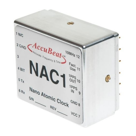
2.5. Recommended Operating Characteristics The NAC1 pinout is shown above in Figure 1. The electrical function of each pin is defined in this section. Refer to the Reference Section for a detailed functionality description of each pin. PIN # NAME... -
Page 11: Evaluation Kit
3.1. Installing the NAC1 on the evaluation board In an ESD- safe environment carefully remove the NAC1 and the evaluation board from their ESD protective bags. Note that the NAC1 pinout is “keyed” (see Figure 1) so the NAC1 can only be inserted in the proper orientation. -
Page 12: Installing The Nac1 Gui Software
7 and having at least one available RS232 (COM) or USB port. Note that multiple NACs can be monitored from a single PC, provided additional COM ports are available. To install the NAC1 GUI software, insert the provided CD-ROM into the CD drive of the PC. The installation will not start automatically. -
Page 13: Figure 4 : Labview85Runtimeenginefull Installation
The directories will be unzipped and the following installation messages will open: Figure 4 : LabVIEW85RuntimeEngineFull installation Figure 5 : visa441runtime installation Finish both installations by clicking three times the "Next >>" button. Restart your PC. Document No. ZD24010 Rev. B2 NAC1 User Manual 13 of 38... -
Page 14: Cabling
6V DC power supply VCC and Ground respectively. NAC1 signal outputs and inputs are available from the evaluation board on connectors J97 (10 MHz Output), J38 (1PPS Output) and J37 (1PPS Input). Connect either (or both) of these to your test equipment (1PPS Input reference, frequency counter, spectrum analyzer, etc.). - Page 15 1PPS Input (BNC) – The 1PPS input connection to the evaluation board accepts a 1PPS reference of arbitrary amplitude (logic high: 2.5V < Vin < 5V) and passes it directly to the NAC1. 1PPS Output (BNC) –The 1PPS output can be buffered by a CMOS 0-3.3 V logic gate on the evaluation board.
-
Page 16: Initial Start Up
3.5. Initial Start Up 3.5.1. Initial Power-On Make sure NAC1 is placed on its socket on the Evaluation board with the protective sheet. Connect the Evaluation board voltage input to the Power Supply. Connect power and RS232 to the Evaluation Board as described in Section 3.3. -
Page 17: Basic Nac1 Gui Features
3.5.3. Basic NAC1 GUI Features The ‘Read Parameters’ button triggers the read of the NAC1 status and setup. The ‘Rx Reading’ indicator will be lit during the process of data acquiring. The ‘Received Data’ window is basically used for the visual confirmation of the last issued command. -
Page 18: Frequency Tuning
3.5.4. Frequency Tuning The ‘Frequency Tuning’ dialog allows tuning the NAC1 microwave synthesizer by applying corrections or setting an explicit frequency value. Corrections are sent in steps of 7.6E-13, 1.96E-10 or 4.98E-8 and can be positive or negative with an arbitrary number of steps. Moreover, corrections can be applied for the current session only (until power down) or forever. -
Page 19: Functional Description
This results in an improved stability of the clock’s output and low sensitivity to disturbances. In addition, the vapor cell in NAC1 is based on a proven traditional glass technology which has been used in Rubidium Clocks for dozens of years. This assures very high reliability and confidence in the design. -
Page 20: Built-In Test (Bit)
Successful BIT result indicates that the internal TCXO is locked on the Physics Package. You can expect the ‘BIT’ to turn ‘OK’ (Green) in 3 minutes after the NAC1 power-up at a room temperature (25 ºC) or up to 10 minutes at -20 ºC. -
Page 21: 10 Mhz Output Characteristics
4.3. 10 MHz Output Characteristics The buffered CMOS clock output at 10 MHz is provided on Pin # 12 of the NAC1. The output series impedance is 200 Ω. For reference, the output driver circuit of the NAC1 is shown below in Figure 10. -
Page 22: Frequency Adjustments
Figure 11 : Evaluation Board 10MHz Output Driver The 10MHz output appears on Pin # 12 as soon as the NAC1 is powered on and is always present until Power-down. When the NAC1 is out of lock (BIT = 1, FLL status = 1), the output frequency is provided by the free-running TCXO, which has frequency accuracy specification of ≈... -
Page 23: Rubidium Free Run
A Rubidium clock (locked or unlocked to GPS), Cesium clock or GPS receiver can be used as a 1PPS source for the NAC1. It is most important to use an accurate 1PPS source, since the NAC1 disciplines to the external 1PPS source. If the 1PPS input is accurate, then the NAC1 is accurate as well. -
Page 24: Disciplining Mode
The 1PPS disciplining uses a DPLL (Digital Phase Locked Loop) algorithm to discipline the Rb frequency to an external 1PPS. A phase meter is implemented within the NAC1 for improved synchronization (< 100 ns) as well as for frequency calibration of the NAC1. The phase meter measures the time difference between the internal NAC1 1PPS (Pin #10) and the externally applied reference 1PPS (Pin #9). - Page 25 Hold Over (state 3). • In case the user sends a ‘SDM 0’ instruction, the NAC1 will immediately be set to Hold Over (state Note: When using the disciplining mode, the NAC1 frequency accuracy is derived from the accuracy of the 1PPS input source.
-
Page 26: Appendices
6. Appendices Appendix A: Mechanical ICD Figure 12 : Mechanical ICD (NAC1004) Document No. ZD24010 Rev. B2 NAC1 User Manual 26 of 38... -
Page 27: Appendix B: Electrical Icd
'0' = Normal operation, '1' = Alarm Power input 3.3±0.1 VDC Control and monitor interface Serial RS232, format CMOS compatible, 3.3V@1MΩ, Comm. 115200BPS Table 3 : Electrical ICD (NAC1004) Document No. ZD24010 Rev. B2 NAC1 User Manual 27 of 38... -
Page 28: Appendix C: Software Icd (Cli)
- Will set the echo ON when used with a terminal application to configure the SEO Y<cr> system mode. - Will cause the system to reply "SEO Y" to indicate that the echo mode is SEO<cr> used in the system. Document No. ZD24010 Rev. B2 NAC1 User Manual 28 of 38... - Page 29 If the operator enters characters that do not match one of the parameters in a CLI command the following error message will be reported: "Invalid command" 9. Case sensitivity: Both commands and their parameters can be entered in uppercase or lowercase letters. Document No. ZD24010 Rev. B2 NAC1 User Manual 29 of 38...
- Page 30 RST - Reset Unit RFC - Rubidium Frequency Correct SDM - Set Disciplining Mode SED - Set External 1PPS input Propagation Delay Set Output Propagation Delay SPD - - User Monitor Report Document No. ZD24010 Rev. B2 NAC1 User Manual 30 of 38...
- Page 31 VER – Report Version This command generates a version report in the following form: VER Model,PN,Mver,Sn,SW_Ver,FW_Ver - Unit model (Up to 4 characters. Example - "NAC1") Model - Part number (Up to 7 characters. Example - "NAC1-00") - Model revision (Up to 2 characters.
- Page 32 - Number of frequency change steps, as a signed value (-127 ÷ 127). Note: Use frequency corrections with caution! Uncontrolled correction can cause an offset to the clock frequency. Document No. ZD24010 Rev. B2 NAC1 User Manual 32 of 38...
- Page 33 Use this CLI command to set external 1PPS output propagation delay. SPD x x = Delay, in ns units. (Range: -500,000,000 ÷ 500,000,000 ns, Default: 0ns). The parameter will be saved in a non-volatile memory. Document No. ZD24010 Rev. B2 NAC1 User Manual 33 of 38...
- Page 34 0, 1, 2 – 1PPS input exists and disciplining mode is enabled (‘SDM 1’). 3 – 1PPS input does not exist or disciplining mode is disabled (‘SDM 0’). - External 1PPS status (1 = Exists, 0 = Does not exist). EXT_PPS Document No. ZD24010 Rev. B2 NAC1 User Manual 34 of 38...
-
Page 35: Appendix D: Specifications
Incorporating proven traditional glass technology and based on Coherent Population Trapping (CPT), the NAC1 is an extremely small and compact atomic clock that has been designed as a board mounted component. NAC1 provides 10 MHz and 1PPS outputs and short term stability (Allan Deviation) of 2E-11 @ 100 seconds with aging of 3E-10/month at 25°C. - Page 36 Ph ys i ca l S pe cif i cat io ns Ph ys i ca l S pe cif i cat io ns Size 41.1mm X 35.8mm X 22mm Weight <75g Document No. ZD24010 Rev. B2 NAC1 User Manual 36 of 38...
- Page 37 -40°C to 85°C but the clock is locked at operating -20°C to 65°C only temperature *After 30 days of continues operation All specifications at 25ºC, Vcc =3.3VDC unless otherwise specified Document No. ZD24010 Rev. B2 NAC1 User Manual 37 of 38...
- Page 38 How to Order AccuBeat P/N Wave Form Special Features Frequency NAC1004 10MHz Square Standard NAC1C04 10MHz Square Without pin 11 Evaluation Kit AccuBeat P/N Description Evaluation Kit NAC1 Evaluation Kit AA50766 Document No. ZD24010 Rev. B2 NAC1 User Manual 38 of 38...
Need help?
Do you have a question about the NAC1 and is the answer not in the manual?
Questions and answers