Table of Contents
Advertisement
Advertisement
Table of Contents

Related Manuals for Milltronics COMPU-M

Summary of Contents for Milltronics COMPU-M
- Page 1 COMPU-M INTEGRATOR Instruction Manual PL-516 April 2001 33455160 Rev. 2.2...
- Page 2 We welcome all suggestions for improvement. Technical data subject to change. MILLTRONICS®is a registered trademark of Siemens Milltronics Process Instruments Inc. Contact SMPI Technical Publications at the following address: Technical Publications Siemens Milltronics Process Instruments Inc.
-
Page 3: Table Of Contents
Compu-M Current Output Isolator Cabling Options INSTALLATION Compu-M Outline and Mounting Compu-M Layout Interconnection System Diagram Compu-M / Belt Scale Compu-M / MMI-2 Compu-M / Speed Sensor Compu-M / Flowmeter Ancillary Connections Power Connections PROGRAMMING Operating Modes Keypad Parameter Entry... - Page 4 APPLICATIONS Belt Scales Operation Initial Start Up Linearization Programming Chart - Example Recalibration Solids Flowmeters Operation Test Rate Initial Start Up Linearization Programming Chart - Example Recalibration PARAMETERS PROGRAMMING CHART PL-516...
-
Page 5: General Information
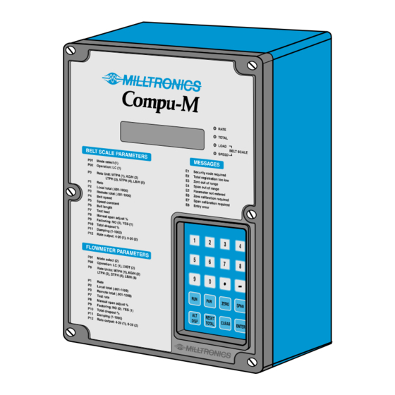
The Compu-M is a microprocessor based integrator designed specifically for bulk dry solids in-line weighing applications. If the current material transport system is by conveyor belt, the Compu-M is used in conjunction with a belt scale. The Compu-M provides a local display of: load, speed, flowrate and total flow. - Page 6 PL-516...
-
Page 7: Specifications
SPECIFICATIONS COMPU-M » 100/115/200/230 V ac ± 10%, 50/60 Hz, 15 VA Power : » standard : » 12 ± 2 V dc, 15 W » optional : » 24 ± 4 V dc, 15 W Environmental : » location : »... -
Page 8: Current Output Isolator
* EMC performance available upon request CURRENT OUTPUT ISOLATOR (optional) Model : » LIs-1 loop isolator Input : » 4-20 mA dc (from Compu-M) Output : » 4-20 mA dc into 600 ohms maximum Common Mode Rejection : » 100 dB at 50 Hz Weight : »... -
Page 9: Cabling
CABLING Load cell : » single, non-sensing : » Belden 8404, 4 wire shielded, 20 AWG or equivalent » maximum run 150 m (500 ft.) » single, sensing : » Belden 9260, 6 wire shielded, 20 AWG or equivalent » maximum run 305 m (1000 ft.) »... - Page 10 PL-516...
-
Page 11: Installation
COMPU-M The Compu-M should be mounted in an area that is within the units ambient temperature range, and is suitable for the specified enclosure. The front cover should be accessible for programming and viewing. -
Page 12: Outline And Mounting
(10.5") mounting holes suitable location for conduit entrances (accessed under lid enclosure 4.3 mm (0.17") dia. Milltronics recommends using a punch 4 places customer for making holes in enclosure. mounting screw Non metallic enclosure does not provide grounding between connections. -
Page 13: Compu-M Layout
COMPU-M LAYOUT board board A board B Isolator (optional) All field wiring must have insulation suitable for at least 250 V. dc terminals shall be supplied from an SELV source in accordance with IEC-1010-1 Annex H. PL-516... -
Page 14: Interconnection
Load cell or LVDT, speed sensor, analog mA output, auto zero and low voltage contact wiring may be run in a common conduit. However, these may not be run in the same conduit as high voltage contact or power wiring. SYSTEM DIAGRAM Compu-M load sensor (e.g. beltscale or flowmeter) -
Page 15: Compu-M / Belt Scale
COMPU-M / BELT SCALE INTERCONNECTION LVDT Compu-M scale junction box SINGLE LOAD CELL * Compu-M scale junction box set switch SW1 on board B to ‘OPEN’ DUAL LOAD CELLS * Compu-M scale junction box PL-516... -
Page 16: Compu-M / Mmi-2
2. Where the integrator to load cell belt scale separation exceeds 150 m (500 ft.) : » A) remove jumpers from Compu-M (board B) TB1 - 19 / 20 and TB1 - 21 / 22 » B) run an additional shielded conductor from each of : »... -
Page 17: Compu-M / Speed Sensor
» position ‘3’ for counter-clockwise speed sensor shaft rotation. Speed sensor shaft rotation is viewed from the front cover side of the speed sensor enclosure. If a speed sensor is not used, a jumper must be connected across Compu-M (board B) TB1 - 13 / 14 PL-516... -
Page 18: Compu-M / Flowmeter
2. Where the integrator to load cell belt scale separation exceeds 150 m (500 ft.) : » A) remove jumpers from Compu-M (board B) TB1 - 19 / 20 and TB1 - 21 / 22 » B) run an additional shielded conductor from each of : »... -
Page 19: Ancillary Connections
1. Auto Zero dry contact may be provided by a material prefeed control device, such that the contact is closed when the material feed is stopped. 2. Analog output must not be grounded, 750 Ω maximum load. 3. Compu-M to LIs - 1 isolator wiring by Milltronics if isolator is factory installed. PL-516... - Page 20 REMOTE SWITCHES RESET SPAN ZERO DISP 1. Relay contacts are rated for 5 A @ 250 V ac. 2. Remote pushbutton switches normally open style, supplied by Milltronics only on particular Compu-M arrangements. PL-516...
- Page 21 REMOTE TOTALIZER Compu-M (board B) 1. Refer to remote totalizer manufacturers instructions for wiring and power requirements. 2. If totalizer power is 24 V dc or less the remote totalizer wiring may be run in a common conduit with any combination of :...
-
Page 22: Power Connections
A circuit breaker or switch in the building installation, marked as the disconnect switch, shall be in close proximity to the equipment and within easy reach of the operator. Connect the Compu-M via terminal 28 to protective earth / ground. DC Power 12 V dc Model... -
Page 23: Programming
LED on the Compu-M front cover is illuminated. All operator programmed information is maintained in non-volatile EEPROM memory and therefore is retained in the event of a power interruption. The Compu-M will return to the previous operating mode when power resumes. -
Page 24: Parameter Entry
PARAMETER ENTRY Specific application information must be entered into the appropriate Compu-M memory locations. These locations are identified by a parameter number (P#). The information entered is referred to as a parameter value (value). To enter specific application information the operator accesses the desired parameter, views the parameter value on the LCD display, and then accepts or alters the current parameter value. -
Page 25: Display Messages
"ENTER" PARAMETER RESET This feature returns the Compu-M memory to factory settings. The implementation of a reset: requires total parameter re-entry, zero and span recalibration, and resets the local totalizer to 0. Refer to Parameter Listing P99 for details. - Page 26 PL-516...
-
Page 27: Operation
If the Compu-M is to be utilized with a belt scale that is installed on a variable incline conveyor (such as a stacker), an Incline Compensator should be used. The Incline Compensator automatically corrects the load cell(s) signal variation caused by a change in conveyor incline. -
Page 28: Initial Start Up
P11 or P18. Remote Totalizer Contact The Compu-M provides a relay contact closure which may be utilized to operate an external device such as a remote totalizer. The on-time duration of the relay contact closure is operator selectable (P16) to suit the external device connected. - Page 29 With the conveyor stopped and locked out, lift the belt off the weighing idlers if possible. Suspend a test weight on the load cell B side of the scale test weight bar. Ensure Compu-M board B switch SW 1 is in the CLOSED position.
- Page 30 Adjust the Compu-M, board B, A BAL potentiometer (P3) as required until the displayed value equals 0 + 5 counts. Remove the test weight and ensure Compu-M board B switch SW1 is in the CLOSED position. Where the dual load cell balance procedure is performed on a previously calibrated system, a new zero and span calibration must be performed.
- Page 31 Programming and Calibration The following parameters are in the Automatic Parameter Access (APA) loop. Press once to accept "ENTER" the current parameter value and proceed to the next parameter. To alter a parameter value, key in the new value and press .
- Page 32 press "ENTER" displayed, Belt Length = 0 0.000] key in value, (Belt Length, as measured or from Design Data Sheet) press "ENTER" displayed, Test Load = 100% Design Load ####] key in value, (Test Load, from Design Data Sheet. Refer to the associated belt scale instruction manual.) press "ENTER"...
- Page 33 (P4). Record the new P4 value on the Programming Chart. If the Compu-M Speed Input is supplied by a Speed Sensor the preceding steps will have altered the Speed Constant (P5). Record the new P5 value on the Programming Chart.
- Page 34 Optional Material Test Material tests are performed to verify the accuracy of the Compu-M span calibration. If the material tests indicate a repeatable calibration deviation exists, a Manual Span Adjust (P8) is performed. This procedure automatically alters the Span calibration and adjusts the Test Load (P7) value accordingly. Subsequent span recalibration utilizing the Test Weight or Test Chain will provide more accurate calibration results.
-
Page 35: Linearization
Conveyor applications where the belt scale is poorly located, or where there is a high degree of variation in belt tension, typically cause the belt scale to report load non-linearly. The Compu-M provides a linearizing function (P24) in order to correct for the deficiency in the weighing system and to provide an accurate report of the actual process. - Page 36 100% of the design rate, followed by material tests and manual span adjust, three material tests were performed at 50, 100 and 150 t/h, as indicated by the Compu-M. The following data was tabulated. (This example is exaggerated for emphasis).
- Page 37 After performing the initial span or after running a material test P10, P11, P12, P13, P14, P16, P17, and P18 may be altered to enhance the display readings and rate output of the Compu-M. These direct access parameters are explained in detail in, Parameters.
-
Page 38: Programming Chart - Example
PROGRAMMING CHART - EXAMPLE ( BELT SCALE ) PROGRAMMING CHART P01 MODE: 1 = belt scale, 2 = flowmeter P02 OPERATION: 1 = load cell, 2 = LVDT P0 UNITS: rate display, 1= MTPH, 2 = KG/H, 3 = LTPH, 4 = STPH, 5 = LB/H P1 DESIGN RATE: [ 2000... -
Page 39: Recalibration
Some parameters interact with others. After altering a parameter value, check all other parameter values. The Compu-M may have altered one or more interacting parameters automatically. Record all parameter value changes on the Design Data Sheet and Programming Chart for future reference. - Page 40 Initial Zero select P77 press "ENTER" displayed [P77 press "1" press "ENTER" displayed [P77 press "ENTER" displayed, wait (time dependent upon the value of P30) ####] displayed [od 0.000] press "ENTER" displayed, New Zero Count, zero calibration complete ####] Direct Zero Entry Direct entry is intended for use when replacing software or hardware and it is not convenient to perform an initial zero at that time.
- Page 41 Routine Span To perform a routine span recalibration, stop the conveyor belt and suspend the test weight from the scale calibration weight bracket or place the test chain on the belt. Refer to associated scale manual. Run the belt, empty (except for the test chain, if used) at normal operating speed press "SPAN"...
- Page 42 Direct Span Entry Direct entry is intended for use when replacing software or hardware and it is not convenient to perform an initial span at that time. select P68 press "ENTER" [P68 0] displayed press "1" press "ENTER" [P68 1] displayed press "ENTER"...
- Page 43 Connect a dry contact activated by a material prefeed control device such as a prefeed motor, material control gate, or valve to board B 1TB-1 and 2 of the Compu-M. The contact must be closed while the material prefeed is stopped.
- Page 44 PL-516...
- Page 45 P11 or P18. Remote Totalizer Contact The Compu-M provides a relay contact closure which may be utilized to operate an external device such as a remote mounted totalizer. The on-time duration of the relay contact closure is operator selectable (P16) to suit the external device connected.
-
Page 46: Test Rate
Alarm The Compu-M provides a programmable relay for alarm (P20) on material rate, or auto zero out of range. If enabled, the relay is energized under normal operation. Under alarm condition, the relay is de-energized and the display flashes. Upon return to normal operation, the alarm state is cleared and the relay energized. If the relay is programmed for auto zero the alarm is in effect until an auto zero within range occurs, when a calibration is initiated or when the rate exceeds 12% of design. - Page 47 Programming And Calibration The following parameters are in the Automatic Parameter Access (APA) loop. Press once to accept "ENTER" the current parameter value and proceed to the next parameter. To alter a parameter value, key in the new value and press .
- Page 48 TO ENTER THE RUN MODE FOR NORMAL OPERATION "RUN" Automatic Parameter Access (APA) programming complete. Further programming, if desired, to enhance the performance of the Compu-M requires parameter programming outside of the APA loop. These parameters must be directly accessed. ie. Press...
- Page 49 Optional Material Test Material tests are performed to verify the accuracy of the Compu-M span calibration. If the material tests indicate a repeatable calibration deviation exists, a Manual Span Adjust (P8) is performed. This procedure automatically alters the Span calibration and adjusts the Test Rate (P7) value accordingly. Subsequent span recalibration utilizing the Test Weight will provide more accurate calibration results.
-
Page 50: Linearization
Where the flowrate reported by the Compu-M is non-linear due to material characteristics, compensation may be achieved by using the linearizer function. The Compu-M provides a linearizing function (P24) in order to correct for the deficiency in the weighting system and to provide an accurate report of the actual process. - Page 51 100% of the design rate, followed by material tests and manual span adjust, three material tests were performed at 12.5, 25 and 37.5 t/h, as indicated by the Compu-M. The following data was tabulated. (This example is exaggerated for emphasis).
- Page 52 Program the Compu-M as follows: P24 = 1 L1 = 12.5 L1c = - 14.3 L2 = 25 L2c = 10.5 L3 = 37.5 L3c = - 8 Often only one point of compensation is required, usually at a low load value. In the prior example, if compensation was only required at 11.6 kg/m, the programming could be as follows.
-
Page 53: Programming Chart - Example
PROGRAMMING CHART - EXAMPLE ( FLOWMETER ) PROGRAMMING CHART P01 MODE: 1 = belt scale, 2 = flowmeter P02 OPERATION: 1 = load cell, 2 = LVDT P0 UNITS: rate display, 1= MTPH, 2 = KG/H, 3 = LTPH, 4 = STPH, 5 = LB/H P1 DESIGN RATE: [ 1200 from design data sheet... -
Page 54: Recalibration
Some parameters interact with others. After altering a parameter value check all other parameter values. The Compu-M may have altered one or more interacting parameters automatically. Record all parameter value changes on the Design Data Sheet and Programming Chart for future reference. - Page 55 Initial Zero select P77 press "ENTER" displayed [P77 press "1" press "ENTER" displayed [P77 press "ENTER" displayed momentarily then, ####] displayed [od 0.000] press "ENTER" displayed, New Zero Count, zero calibration complete ####] Direct Zero Entry Direct entry is intended for use when replacing software or hardware and it is not convenient to perform an initial zero at that time.
- Page 56 Routine Span To perform a routine span recalibration, ensure material flow is stopped and the prefeed is locked out. Attach the test weight to the flowmeter sensing plate. Refer to the associated flowmeter manual. press "SPAN" displayed, Current Span Count [SP ####] press "ENTER"...
- Page 57 Connect a dry contact activated by a material prefeed control device such as a prefeed motor, material control gate, or valve to board B 1TB-1 and 2 of the Compu-M. The contact must be closed while the material prefeed is stopped.
- Page 58 PL-516...
- Page 59 1 = belt scale (F) 2 = flowmeter Operation Defines the type of transducing element utilized to provide the load signal input to the Compu-M. enter: 1 = load cell (F) 2 = LVDT Rate Units Defines the desired Rate Display engineering units of measure.
- Page 60 Enter a higher value. Remote Total Defines the amount of material to be registered by the Compu-M prior to initiating a relay contact closure which may be utilized for remote totalization. The weight unit portion of the Rate Unit (P0) selected is assumed.
- Page 61 Test Load (Belt Scale Applications Only) Defines the load to be registered by the Compu-M when the Test Chain or Test Weight is applied to the Belt Scale. Enter the value that is indicated on the Design Data sheet. Entering "0" or performing a Reset will return the Test Load to the 100% Design Load factory value.
- Page 62 Test Rate (Flowmeter Applications Only) Defines the desired Rate to be registered by the Compu-M when the Test Weight is applied to the flowmeter. Refer to the associated flowmeter instruction manual for assistance with calibration procedures, and Test Weight or Test Rate calculations.
- Page 63 The following display values are not crucial but represent typical Compu-M displays. If P12 = 1, (4 mA min. output) the Compu-M will display a value ≅ 600. If P12 = 2, (0 mA min. output) the Compu-M will display a value ≅...
- Page 64 When this parameter is accessed the Compu-M will display a value ≅ 3300, the mA output will be 20 mA. To increase the output press .
- Page 65 Prior to the initial entry of a value into this parameter, the current dynamic belt speed is displayed. If the speed displayed by the Compu-M is not equal to the actual belt speed, enter the actual belt speed. The use of this parameter does not require a system recalibration.
- Page 66 Alarm This parameter sets the alarm function: rate, belt speed or auto zero out of range. The setpoint units for rate alarm are % of design rate, P1. The setpoint units for belt speed are % of design belt speed, P4. The hysterisis for rate alarm and speed alarm is 2% of the design rate (P1) or belt speed (P4), respectively.
- Page 67 Compu-M will utilize to perform a zero or span calibration. For Flowmeter applications; defines the number of time periods the Compu-M will utilize to perform a zero or span calibration (1 time period ≈ 10 seconds).
- Page 68 (F = 0) "ENTER" Software Revision (V) Displays the revision number of the software programmed into the Compu-M EPROM memory at the factory. Check Software Initiates the Compu-M EPROM memory self diagnostic routine. This function is automatically performed during either level of Reset. (P99 = 1, or 9).
- Page 69 "ENTER" 67890] e.g. new count value Initial Zero Activates a Zero calibration which the Compu-M will utilize as a reference to which subsequent routine Zero calibrations will be compared. This parameter is generally utilized in response to a Display Message...
- Page 70 (Belt Scale Applications Only) Displays the count reference value of the summed inputs from load cell A and B when Compu-M board B switch SW1 is closed. Placing the test weight on load cell B side of the belt scale and entering the displayed value automatically advances the display to the next sequential parameter.
- Page 71 Without disturbing the test weight position (P93), the operator adjusts the Compu-M board B "A BAL" potentiometer while observing the effect on the displayed value. The load cell signal inputs are sufficiently balanced when the value displayed equals 0 + 5 counts.
- Page 72 PL-516...
- Page 73 MAINTENANCE The Compu-M requires no maintenance. The enclosure may be cleaned using a vacuum cleaner and a clean, dry paint brush. It is also a good idea to check the associated load sensing device, according to its instruction manual. PL-516...
- Page 74 PL-516...
- Page 75 PROGRAMMING CHART P01 MODE: 1 = belt scale, 2 = flowmeter P02 OPERATION: 1 = load cell, 2 = LVDT P0 UNITS: rate display, 1= MTPH, 2 = KG/H, 3 = LTPH, 4 = STPH, 5 = LB/H P1 DESIGN RATE: from design data sheet P2 LOCAL TOTAL: registration multiplier, refer to parameters...
- Page 76 PL-516...
- Page 77 Siemens Milltronics Process Instruments Inc. 2001 Subject to change without prior notice Siemens Milltronics Process Instruments Inc. *7ml19981dl01* 1954 Technology Drive, P .O. Box 4225 Peterborough, ON.Canada K9J 7B1 Tel: (705) 745-2431 Fax: (705) 741-0466 Printed in Canada www.milltronics.com...
Need help?
Do you have a question about the COMPU-M and is the answer not in the manual?
Questions and answers