Table of Contents
Advertisement
Advertisement
Table of Contents

Summary of Contents for NKT SuperK COMPACT
- Page 1 SuperK COMPACT Instruction Manual...
- Page 2 0239159; EP 1181595; AU 0179603; WO 0214944; AU 0181741; WO 0212931; WO 0212931; EP 1086393; EP 1086391; AU 0035509; WO 0060390; CA 2368789; CA 2334554; CA 2334510; US 7305164. Issue: Published: May 2018 Copyright © 2018 by NKT Photonics A/S. All rights reserved. Reproduction or translations of any part of this work is prohibited.
-
Page 3: Table Of Contents
Section 2: Laser Safety ............................ 3 2.1 General information and designated use ................3 2.2 Labels used on the SuperK COMPACT ..................3 2.3 Safety hazards ........................5 2.4 Laser safety goggles ....................... 5 2.5 Laser safety compliance list ....................6 2.6 Supply power .......................... -
Page 4: General
The safety might be seriously impaired if the instruction manual is not followed carefully. Also, make sure to follow the instructions on how to unpack the SuperK COMPACT from the shipping box if this is not already done. The equipment comprises a laser Class 3B. It is recommended, that only persons familiar with laser safety regulations and coherent light should operate this equipment. -
Page 5: Laser Safety
Furthermore, any other staff in close proximity of the SuperK COMPACT should be aware of any risk in connection with usage of the unit. - Page 6 SuperK COMPACT will be void. For service or support on the system, please refer to section 7.3: Technical support. Figure 2.4: Warranty void label placed on the cover of the SuperK COMPACT. P a g e...
-
Page 7: Safety Hazards
SuperK COMPACT. Even though the SuperK COMPACT is only a Class 3B laser unit, focused IR light Skin burn from the unit could cause potential skin burn. Avoid any contact between laser beam and skin or wear appropriate skin protection if operation close to the beam is required. -
Page 8: Laser Safety Compliance List
UL and CSA Supply power The SuperK COMPACT must be supplied with 100 – 240 VAC through a standard power cable with an IEC type C13 appliance plug, and must be connected to protective earth through this cable. A cable is supplied with the SuperK COMPACT, but it may be exchanged with a compatible type, compliant with the local regulations. -
Page 9: Key Switch
Key Switch The SuperK COMPACT is equipped with a key switch on the front panel. The key Key switch must be switched to the ON position before laser light can be emitted. Whenever the unit is not in use, the key should be removed and kept in a safe place. The laser unit cannot be operated when the key is in the OFF position and the key cannot be removed whenever it is in the ON position. - Page 10 It is not recommended to operate the laser without an appropriate interlock connection to e.g. a door or enclosure around the system. If users bypass this safety feature, NKT Photonics bears no responsibility on damage, loss or harm caused by accidental laser exposure.
- Page 11 When the switch is closed (B) the circuit is closed and it is possible to have laser emission. The remote switch interlock enhances safety, as it shuts off laser emission if the door switch to the room or enclosure where the system is located is opened. If the interlock circuit is opened during operation, the interlock circuit must be reset before laser emission can be initiated again.
-
Page 12: Equipment Description And Installation
SuperK COMPACT. Operating conditions The SuperK COMPACT is specified to operate in the range of 15-30°C in a non condensing environment. The output fiber should not be coiled to less than 10 cm diameter. Do not expose the units to vibrations or mechanical shock during operation. -
Page 13: Front Panel
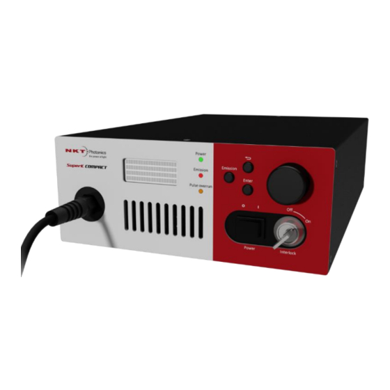
Front Panel The SuperK COMPACT can be operated entirely via the front panel interface. Figure 3.1: Front panel of the SuperK COMPACT system. (A) On / Off SWITCH Turns the electrical power on/off to the laser. Enables/disables interlock or laser emission from the SuperK COMPACT. -
Page 14: Rear Panel
Rear Panel The rear panel of the SuperK COMPACT contains access for communication, power, interlock connection and trigger input/output. Figure 3.2: Rear panel of the SuperK COMPACT system. (A) Power socket 100V-240V/50Hz-60Hz (B) Interlock socket Connector for interlock cable (LEMO connector) (C) USB USB interface. -
Page 15: Operation And System Menu
Wear suitable protection and ensure everyone in the laser area is aware that the system is in operation. Ensure that remote interlock is in place. The SuperK COMPACT is not equipped with a back reflection isolator. Make sure to minimize external back reflections into the laser. External back reflections can compromise performance and ultimately damage the laser. - Page 16 The SuperK COMPACT may be operated in different modes. Table 4.2; 4.3; 4.4 and 4.5 describes the operating procedures for the different operating modes. The laser can run with internal trigger mode. The resolution of the different modes is dependent on the maximum frequency available and the hardware. If a more precise setting of frequency/repetition rate is wanted, the laser must be run in external trigger mode.
- Page 17 Use the following procedure to operate the SuperK COMPACT using the external trigger: Check that the external trigger source delivers a trigger signal between 0-4 volt with a frequency less or equal to the maximum laser frequency. Connect the external trigger source to the “COAX TRIG INPUT”...
- Page 18 Use the following procedure to operate the SuperK COMPACT using the external gate mode: Check that the external trigger source supplies a trigger signal between 0-4 volt. Connect the external trigger source to the “COAX TRIG INPUT” (see figure 8).
-
Page 19: Superk Compact With Fc Output Connector
(lint free wipes) or similar appropriate material may be applied. SuperK COMPACT with collimated output The SuperK COMPACT can also be supplied with an armored fiber delivery, terminated by a collimator, see figure below. The collimator consists of two parts: ... - Page 20 Figure 4.5: NKT Photonics collimator holder, part no. A000-000-002 Warnings If the collimator is scratched it might not fit into the collimator input in the SuperK accessories.
-
Page 21: Display Messages
Display messages Warning and error messages Before and during operation, the SuperK COMPACT laser will show various messages in the display. Some of these indicate errors or other circumstances that prevent the unit from functioning - others are merely information to the operator. -
Page 22: Trigger Input And Remote Connection
Section 6: Trigger input and remote connection Trigger operating modes The selected operating mode determines when and how often the light source generates an optical pulse. The operating mode can be selected in the front panel menu or via the USB/RS-232 port. Most operating modes use some additional settings: Frequency (repetition rate) and/or Burst count. -
Page 23: Remote Interface Connection
Remote connection COMPACT unit for communication with the unit through a computer. The serial communications port on the SuperK COMPACT is a standard USB port, designed for connecting to a standard PC USB-port. In order to connect the SuperK COMPACT to a computer for remote operation please use a standard USB cable with A to B connectors as indicated in figure 6.1. -
Page 24: Industrial Trigger Input
Pulse width: Min. 200 ns Trig level (adjustable): Min. 0 V; max. 4 V Hysteresis: Approx. 1 % Connector type: Max trigger frequency: 200 kHz Industrial trigger input This input is isolated electrically from the light source, which allows the operator to connect the input to a wide variety of equipment. -
Page 25: Service & Support
If cleaning of the SuperK unit is required the chassis may be cleaned with a damp Chassis cloth. Do not use solvents for cleaning the chassis. If required the SuperK COMPACT should be stored in a dry and cool place. The Storage optical output should be protected using supplied caps. Avoid exposing the unit to any vibrations or mechanical shocks. -
Page 26: Technical Support
If the fiber facet is damaged the connector must be re-polished before operation of the SuperK COMPACT can continue. Failing to do so could result in incorrect measurements/usage or even damage to the laser unit itself. -
Page 27: Specifications Of The Superk Compact
Section 8: Specifications of the SuperK COMPACT Electro-mechanical Specifications Environmental Temperature, operating 15-30 °C Temperature, storage, non condensing 5-50 °C Humidity, non condensing 20-80 % RH Power Power consumption, nominal with no accessories 40 W connected Power consumption, maximum 150 W Line 100 –... -
Page 28: System Dimensions
System dimensions Dimensions: All dimensions in mm P a g e | 26... -
Page 29: Accessories For The Superk Compact
LLTF Tunable High Contrast Filter is a continuously tunable high-resolution bandpass filter that effectively converts a NKT Photonics’s supercontinuum source into a widely tunable picosecond laser. The filter transmits, with high efficiency, a single laser line while blocking unwanted lines with excellent out-of-band suppression. -
Page 30: User Notes
User Notes P a g e | 28... - Page 31 NKT Photonics Blokken 84 3460 Birkerød Denmark Phone: +45 43483900 Fax: +45 43483901 www.nktphotonics.com...
Need help?
Do you have a question about the SuperK COMPACT and is the answer not in the manual?
Questions and answers
Hello, is it possible to tune the output power of the laser or I just need to use neutral density filters to lower it down?
The output power of the NKT SuperK COMPACT laser is not explicitly stated as tunable in the provided context. To reduce the output power, neutral density filters or attenuators at each output exit should be used for flexibility.
This answer is automatically generated