Table of Contents
Advertisement
EGM-4 Environmental Gas
Monitor For CO
2
Operator's Manual
Version 4.19
For Firmware (EPROM) Version 1.46 and Greater
© 2012 PP Systems. All Rights Reserved
14 February 2013
PP Systems
110 Haverhill Road, Suite 301
Amesbury, MA 01913 U.S.A.
Tel: +1 978.834.0505
Fax: +1 978.834.0545
Email:
support@ppsystems.com
Web Site:
http://www.ppsystems.com
Advertisement
Table of Contents

Summary of Contents for PP Systems EGM-4
- Page 1 EGM-4 Environmental Gas Monitor For CO Operator’s Manual Version 4.19 For Firmware (EPROM) Version 1.46 and Greater © 2012 PP Systems. All Rights Reserved 14 February 2013 PP Systems 110 Haverhill Road, Suite 301 Amesbury, MA 01913 U.S.A. Tel: +1 978.834.0505 Fax: +1 978.834.0545...
- Page 2 This page left intentionally blank for printing purposes.
-
Page 3: Table Of Contents
LCD Display ....................14 Gas Ports ....................14 Battery ......................14 Powering The EGM-4 With Internal 12V NiMH Battery ....... 14 CHARGING THE INTERNAL 12V NiMH BATTERY ............15 Charge Cycle and LED Indications for 12V NiMH Battery Charger ......... 15 Charge Socket .................... - Page 4 Alarm Setpoint ................33 Setting the High CO Alarm Setpoint ................34 7VOUT ..........................34 3CAL ......................35 Connecting Calibration Gas To The EGM-4 ..............35 4DMP ......................36 Screen Display ......................... 36 Data Dump ........................37 ® Transferring Stored Data Using The Windows Based Software Program .....
-
Page 5: Preface
User Registration It is very important that ALL new customers register with us to ensure that our user’s list is kept up to date. If you are a PP Systems’ user, please register yourself electronically on our web site at http://www.ppsystems.com/user_registration2.htm... -
Page 6: Warning Notice
If the EGM-4 is supplied on its own, we do NOT supply any external filters. If the EGM-4 is used in conditions where there is risk of condensation or water in the sample line, (i.e. -
Page 7: Pp Systems' Contact Information
(Hydrophobic) on page 52. Very Important If there is any risk of of water entering the EGM-4, you must protect the instrument by using an external 3 µm hydrophobic filter (Part No. 10045-1) or water drop out trap. We strongly recommend using 3 µm filters as any other size may cause damage to the pump. -
Page 8: Technical Specification
12 V, 2.0 Ah Rechargeable Lead Acid Battery providing up to 4 hours continuous use or 12V NiMH rechargeable battery providing up to 8 hours continuous use. Longer times available with external 12V battery. Battery life may be reduced when EGM-4 is used with add-on sensors/accessories. Gas Connections Two barbed fittings (inlet and exhaust) for 1/8”... -
Page 9: Introduction
8 hours continuous use. For extended operation in the field, PP Systems can also provide an external power supply cable that will allow you to connect up to an external 12 V battery. If interested, please contact PP Systems (See Systems’... -
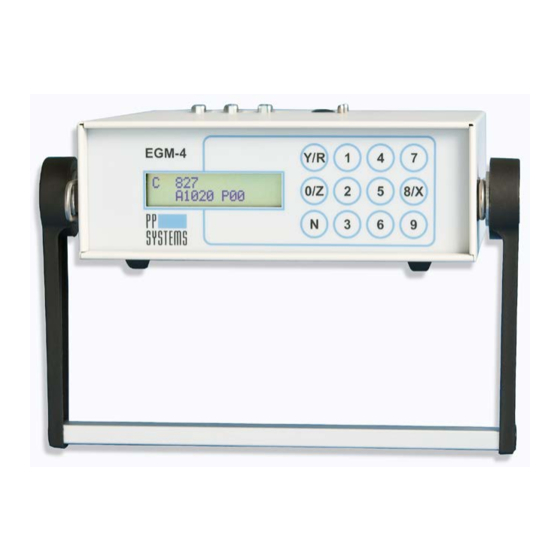
Page 10: Getting Familiar With The Egm-4
Getting Familiar With The EGM-4 Getting Familiar With The EGM-4 LCD Display Custom, (2 x 16) tactile Character keypad Front Panel Figure 1 EGM-4 Display (Front Panel) RS232 Connector 4-20 mA Access Hole Gas In Port Sensor I/O Connectors Gas Out Port EGM-4 Operator's Manual –... - Page 11 Getting Familiar With The EGM-4 Top of EGM-4 Back Panel of EGM-4 fitted with 12V Lead Acid Battery Back panel of EGM-4 fitted with 12V NiMH Battery EGM-4 Operator's Manual – Version 4.19 - 11 -...
-
Page 12: Environmental Sensor Inputs (I/O Ports)
0-1V input. Note, the sensor inputs are displayed in mV (i.e. 0-1,000 mV) instead of Volts. If one of our environmental sensors is used with the EGM-4, it must be plugged into the instrument prior to turning it on. The EGM-4 automatically detects the sensor connected as a result of code resistors which are fitted to the 15 pin D Connector between pins 1 and 6. -
Page 13: Analog Output
Getting Familiar With The EGM-4 Analog Output The EGM-4 has two 15 pin I/O connectors with a 0-5V analog output. The default output is set at 0-5V. However, this can be changed by the user (if required) to any value in between (i.e. -
Page 14: Soda Lime
The EGM-4 features a 2x16 character, backlit LCD display. Gas Ports There are two barb fittings located on the top of the EGM-4. Each barb fitting is designed for use with 1/8” (.125”) ID tubing. One barb fitting is labelled “Gas In” and the other “Gas Out”. -
Page 15: Charging The Internal 12V Nimh Battery
All systems are supplied complete with an AC Adapter/Charger designed specifically for use with the EGM-4 for charging the internal 12 V 2.0 Ah lead acid battery and for continuous operation in the lab. This unit has the following technical specification:... -
Page 16: Power Switch
14. Power Switch To power up the EGM-4, the On/Off Switch should be toggled to the “On” position. To turn the instrument off, the switch should be toggled to the “Off” position. EGM-4 Operator's Manual – Version 4.19... -
Page 17: Operation
The EGM-4 is a menu driven instrument. Note. If any external sensors/probes are to be used with the EGM-4, they MUST be electrically connected to one (or both) of the I/O ports prior to turning the instrument on. When the instrument is first powered up, it will go through its normal warm-up period that takes approximately 5 minutes. - Page 18 Refers to the probe/sensor connected to the EGM-4. For a list of probe types, see Environmental Sensor Inputs (I/O Ports) on page 12. R150 Number of records stored in memory. If the EGM-4 is being used as a porometer (i.e. PMR-5), the following will be displayed: C2000 5V=2000 POROMETER R150 Where: C2000 Corresponds to the last calibration gas concentration.
-
Page 19: Main Menu
Each option is discussed in further detail below. 1REC To begin recording, press key 1. Please note, the EGM-4 display is dependent upon which probe type is connected to it. The following table illustrates the Probe Types: If the EGM-4 is used as a:... -
Page 20: Stand Alone Co Analyzer (Probe Type 0)
Additional information (i.e. external sensors, etc.) may be viewed on the LCD display if required. While in Measurement Mode with the CO concentration displayed, subsequent presses of the 8 key will show additional displays as follows: EGM-4 Operator's Manual – Version 4.19 - 20 -... -
Page 21: Measurement Mode Display Structure
The record number resets each time the instrument starts or when the memory is cleared. It counts up to 9999 and then resets automatically to 1. The internal EGM-4 memory allows data storage of up to 1,000 records. Please note, when the memory is full, it overwrites the oldest records. -
Page 22: Changing Plot Number
The record number resets each time the instrument starts or when the memory is cleared. It counts up to 9999 and then resets automatically to 1. The internal EGM-4 memory allows data storage of up to 1,250 records. Please note, when the memory is full, it overwrites the oldest records. -
Page 23: Pp Systems Environmental Sensor Conversions
Operation PP Systems Environmental Sensor Conversions: The following conversions need to be made to determine actual measurements of PAR, %RH and temperature when using PP Systems’ environmental sensors. PAR Sensor mV x 3 = PAR Level (µmol m %RH Sensor mV / 10 = %RH mV / 20 = Temperature (˚C) -
Page 24: Closed System Soil Respiration (Probe Type 8)
The system always starts up with the SRC-1 default values. See table below for default values for SRC-1 and CPY-4. If using the CPY-4 or non-standard chambers with the EGM-4, press key 1 to change the system volume, key 2 to change the area exposed for the proper values (Display 3):... - Page 25 To return to Display 1 press key 8/X twice. Only the plot number can be changed at this point and the record number automatically resets to 1 when the plot number changes. The next display is as follows (Display 6): CHAMBER FLUSHING HOLD IN AIR EGM-4 Operator's Manual – Version 4.19 - 25 -...
- Page 26 After approximately 5 seconds, the measurement will commence. Before final calculation of soil respiration rate (g (CO Hour) can be achieved, the EGM-4 must have accumulated 4 data sets. The measurement display is as follows (Display 9): C 395 H14.7 T22 A02.11 Q0000 110...
-
Page 27: Oxygen (Probe Type 9)
6 to ensure that you do not encounter any problems related to water in the analyzer. Immediately after pressing key 1, the instrument will display the following message (Display 1): CPY 1:5L 2:20L 3:100L 4:CFX EGM-4 Operator's Manual – Version 4.19 - 27 -... - Page 28 (Assimilation rate) (µmol m Flow Rate (ml/min) Indicates if Reference or Analysis is being sampled If you press the 8/X key, the standard EGM-4 data is displayed (i.e. CO O, etc.). EGM-4 Operator's Manual – Version 4.19 - 28 -...
-
Page 29: Calculation Of Fluxes For Cfx And Cpy Chambers
To return to the Main Menu simply press the N key when either Display 2 or 3 is shown. System Equilibrium The EGM-4 is an absolute analyzer. In order to work with open-type chambers, an internal solenoid (built into the chamber) switches every 30 seconds to select either the reference or analysis sample gas stream for measurement. -
Page 30: 2Set
Press Y if the settings are correct. Press N to change the Probe Type The EGM-4 is quite versatile and can be used as a stand alone gas analyzer, part of an environmental monitoring system when used with any of our available sensors (i.e. TRP-2, SRC-1 Soil Respiration Chamber, CPY-4 Canopy Assimilation Chamber, etc.) or as a steady... -
Page 31: Probe Setting Override
Press 2ZERO to change the zero type and the time interval for performing zeros. Changing the Zero Type Press key 2 (2ZERO) and then key 1 to change the zero type used by the EGM-4. At present, there are 3 types of zeros that can be performed: Auto This is the recommended ZERO type. -
Page 32: Changing The Zero Time
ZERO. On completion of the Analyzer ZERO, the pump will again switch off. By default, the EGM-4 is set to dynamic sampling with the pump on at all times. The general procedure for static measurements is as follows: 1. -
Page 33: 5Recd
The AV defaults to 6 units without a probe (EGM-4 on its own). The default for the EGM-4 when used on its own is 0.3% of full scale. Therefore, for an EGM-4 calibrated to 2,000 ppm, the default value would be 6 ppm. -
Page 34: Setting The High Co Alarm Setpoint
The display will show ?????. Enter the required value. Note, leading zeros are required for values less than 1000 (i.e. 00900 for 900). The default EGM-4 high alarm setpoint setting is 2000. As long as the high alarm is set to the maximum CO ppm range of the instrument, the alarm is inactive. -
Page 35: 3Cal
+/- 1% and traceable to NIST standards. The zero gas will only be accurate if the soda lime in the absorber column is fresh. Assuming that a calibration gas mixture is used to calibrate the EGM-4, follow these instructions: 1. -
Page 36: 4Dmp
Stored data can be viewed on the instrument LCD display or transmitted to your PC computer using our data transfer software. The EGM-4 will store up to 1,000 records in memory. Note, when the memory is full, the oldest record will be overwritten each time additional records are taken. -
Page 37: Data Dump
Note, some of the displays will vary according the probe type connected. Data Dump To transmit stored data from the EGM-4 to a PC, you must use the data transfer cable and software supplied with the system. Step by step instructions on transferring data from the EGM-4 to the PC are contained in the software Help file. -
Page 38: Logging Data
(.) or comma (,). 5. Click OK to proceed. 6. Ensure that the EGM-4 is in Dump Menu (Key 4 from Main Menu). Press key 2 Data Dump on the EGM-4. On the EGM-4 “CONNECT TO PC ANY KEY TO SEND”... -
Page 39: Data Structure Based On Probe/Sensors
Data Structure Based On Probe/Sensors Please note. The data structure, particularly columns A-H described above, is dependent upon the probe/sensor that is connected to the EGM-4. Probe Description of Sensor Each Column is described as follows... -
Page 40: Error Cod
< 50 ˚C failure. (see PP Systems’ Contact Information on page 7) • • Analyzer Possible thermostat Contact PP Systems. temperature > 60 ˚C failure. (see PP Systems’ Contact Information on page 7) EGM-4 Operator's Manual – Version 4.19 - 40 -... -
Page 41: Egm Serial Outputs
Battery voltage < 10.5v Re-charge battery EGM Serial Outputs (For Use With WINDOWS Data Transfer Program or other terminal program) The following data strings are output from the EGM-4 with no user intervention. On Starting: <SP>B, EGM4,Serial Number, Firmware version<CR> <SP>=Space, <CR>=Carriage return. -
Page 42: 6Clk
Cleared” is displayed before returning you to the main menu. If you do not want to clear the database, simply press the N key. 6CLK To view/set the EGM-4 real time clock, press the 6 key. The following message should be displayed: RESET TIME (Y-N)? -
Page 43: Diagnostics And Initialisation
It is important to allow the EGM-4 to warm up for at least 30 minutes prior to checking system diagnostics. To check system diagnostics and to reinitialize the EGM-4, press key 0 with the Main Menu displayed. -
Page 44: Maintenance
Maintenance Maintenance The EGM-4 is virtually maintenance free. However, there are a few items that should be watched and cared for periodically. Soda Lime Absorber Column The soda lime absorber column is built into the EGM-4 and safely protected within the enclosure. -
Page 45: Material Safety Data For Soda Lime
Obtain medical attention if skin becomes inflamed. Eye Contact Irrigate thoroughly with clean water. Obtain medical attention. Ingestion Wash out mouth thoroughly. Drink water. Obtain medical attention. HAZARD LABELLING Transport Codes None required. Hazard Classification None. EGM-4 Operator's Manual – Version 4.19 - 45 -... -
Page 46: Servicing The Egm-4
If it reads 0, you have a good fuse. Anything else, the fuse is bad and should be replaced. The EGM-4 enclosure must be removed in order to service the following items: •... -
Page 47: Inside The Egm-4
5. Connect the new infrared source electrical connector to CN3 on the circuit board. The orientation does not matter. 6. Power up the EGM-4 and allow it to run warm up for 30 minutes. After the warm up period, check the raw IRGA A/D readings with CO -free air. -
Page 48: Checking Egm-4 Raw A/D Readings
Maintenance Checking EGM-4 Raw A/D Readings On the EGM-4, monitor the raw A/D readings on the display. To do so from the main menu (1REC 2SET 3CAL, etc.): 1. Press Key 0 (to go into system diagnostics) 2. Press Key 1 (Diagnostics) The display will show the current A/D readings for the CO analyzer for both “Measure”... -
Page 49: Zero Valve
ZERO Valve If it is suspected that the ZERO valve is not functioning properly, we recommend returning the EGM-4 to our factory for repair as this item is soldered directly to the PC075 circuit board. Contact PP Systems (see PP Systems’ Contact Information on page 7). -
Page 50: 12V Nimh Battery
0.5 kg Removing The 12V NiMH Battery When removing the battery, first ensure that the power to the EGM-4 is turned off. With the enclosure and back panel removed, simply pull out the battery pack as shown below and locate the three terminal connections. The front panel may need to be removed to slide the battery out of its compartment if it is stuck. -
Page 51: Air Sampling Pump
Maintenance Air Sampling Pump The EGM-4 is fitted with a sealed, rotary vane pump to sample the reference air. Rotary vane pump components wear with prolonged use and material from the vanes may build up within the pumps. This can eventually reduce the pumping efficiency or even cause them to stop running. -
Page 52: In-Line Filter Assembly (Hydrophobic)
When finished, run the pump in air for at least 15 minutes to allow any residual alcohol to eVaporate. Ideally, let the pumps dry outside of the EGM-4 overnight. If the pumps are reconnected prematurely, the absorber chemical (soda lime) will be exhausted quicker than usual. -
Page 53: Consumables And Spares For Egm-4
PC073-1 EGM/SBA/WMA Infra-Red Source (Low Range Instruments) PC073-2 EGM/SBA/WMA Infra-Red Source (High Range Instruments) 10020-1 IRGA Tubeset Assembly-Long (For SBA-4, EGM-4, WMA-4, TPS-1 & TPS-2) 10020-2 IRGA Tubeset Assembly-Short (For SBA-4, EGM-4, WMA-4) STD053-1 20mm Fuse, 1A (Qty. 5) STD070... -
Page 54: User Notes
User Notes User Notes EGM-4 Operator's Manual – Version 4.19 - 54 -...
Need help?
Do you have a question about the EGM-4 and is the answer not in the manual?
Questions and answers