Table of Contents
Advertisement
Quick Links
Advertisement
Table of Contents

Summary of Contents for CBE 465
- Page 1 465 CONTROLLER User’s Guide 1 OF 20...
-
Page 2: Table Of Contents
Table of Contents SECTION 1. INTRODUCTION .................. 3 COMMON WEIGHING APPLICATIONS ............3 CONTROLLER DESCRIPTIONS ..............4 Stainless Steel Enclosure ................4 FEATURES ..................... 4 SPECIFICATIONS ..................5 DISPLAY ......................6 KEYPAD ......................7 OPTIONS ......................8 SECTION 2. LEGAL FOR TRADE ................11 OIML AND INTERNATIONAL OPERATION ........... -
Page 3: Section 1. Introduction
Section 1. Introduction GSE 460 Series programmable indicators come standard with a number of features that make them the most versatile and powerful systems in their price class. Even in the most demanding industrial environments, the 460 Series indicators will provide years of quality weighing service. This User’s Guide contains basic operating information. -
Page 4: Controller Descriptions
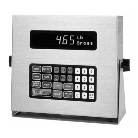
Controller Descriptions All 460 Series models come with a swivel bracket for positioning on a tabletop or mounting to any fixed surface. GSE offers many options to enhance the 460 Series of indicators. The number of options that can be used varies among the different models. See the Specifications section on page 3 for enclosure dimensions. -
Page 5: Specifications
• Selectable weighing units: pounds, kilograms, ounces, grams, etc. • Programmable RS-232 communications software • Remote display support capability • Expandable memory for increased data storage • Battery-backed time and date clock • Enclosure protects against water ingression Specifications Performance •... -
Page 6: Display
• Status indicator 10-character dot matrix prompting display Enclosure Dimensions Model Width Height Depth 465 Stainless Steel 11 in* (279 mm) 9 in* (228 mm) 4.4 in* (112 mm) 10 in** (254 mm) 9 in** (228 mm) 4.4 in** (112 465 Panel Mount mm =millimeter;... -
Page 7: Keypad
• The lower line of the dot matrix area specifies the type of data, such The lower line of the dot matrix area specifies the type of data, such as Gross, Net, Tare, etc. The dot matrix area also displays specific messages during controller operation and setup. -
Page 8: Options
The [F1] key is used as an up arrow key for scrolling or as a function key (such as accessing a menu or starting a process). Not available [F1] on Model 460. Only available on the Model 465. Used as a function key and a down [TARGET] arrow key. Description Press the numeric keys to enter numeric values 0 through 9. - Page 9 4-Position I/O Board 460 Series supports the eight following 4-position I/O boards: • Low Voltage AC 2 input 2 output • High Voltage AC 2 input 2 output • AC 4 output • Low Voltage AC 4 input • High Voltage AC 4 input •...
- Page 10 Network Module Addressable RS-485 network card. Full or half duplex. Profibus Module Allows joint operation of several systems with their distributed peripherals on one bus. The GSE indicator acts as a slave on the network line. RF Communication Module Communicate wirelessly to other indicators, PC or printer. SCR Module DIN rail mount controller suitable for controlling AC devices such as vibratory feeders.
-
Page 11: Section 2. Legal For Trade
Section 2. Legal for Trade The 460 Series parameter setup does not ensure compliance with legal-fortrade installations as mandated by local weights and measures authorities. This chapter explains how to configure the 460 Series controllers to comply with various regulations and describes other features that will make your controller suitable for installations worldwide. -
Page 12: Enabling Ntep Operation
and Technology (NIST). For more information on this and other NIST publications, visit their web site at http://www.nist.gov. Enabling NTEP Operation In order to configure the 460 Series indicators to comply with NTEP requirements, the NTEP parameter (P440) must be enabled in the Setup Mode. This will have the following effects on the standard indicator’s operation: •... -
Page 13: Sealing And Audit Trails
Accessing the Custom Setup List DO NOT ATTEMPT TO ACCESS THE CUSTOM SETUP LIST DURING CRITICAL WEIGHT PROCESSING! It is important to note that all functions of the operating mode will be suspended immediately upon accessing the information parameters. This includes suspension of weight conversions, deactivation of all setpoints and cancellation of custom transmits. - Page 14 The 460 Series panel mount versions use a lead-wire seal and one screw. Table 4: Main Board Jumper Location Model(s) Program Jumper Location 460, 465 14 OF 20...
- Page 15 Audit Trail Parameters Three separate incrementing, non-resettable audit trail parameters are used by the M660 to indicate changes to various parameters: • P60201 – OIML • P60203 – Calibration • P60204 – Setup An audit trail counter will increment only once upon exiting the Setup Mode and saving changes regardless of how many settings were changed.
-
Page 16: Section 3. Troubleshooting
Section 3. Troubleshooting This chapter of the User Guide provides information on error messages and trouble-shooting 460 Series controllers. Some information in this chapter refers to parameters that are not discussed in this guide. They are provided as a quick reference to problems and solutions. -
Page 17: Setup Mode Error Messages
07 Tare < 0 ! Negative tare attempted, but not allowed per P162. For auto- tares, the GROSS Weight must be greater than zero unless P162 is changed to allow negative tares. 08 CheckConn. Displayed if the signal into the A/D is +/- 2 times the Full Scale signal. - Page 18 Contact your GSE distributor. 18 BufSzMax! The accumulative total buffer size for both the TX and RX buffers of all four COMM ports is 4096 bytes. Displayed If entries to the “buffer size” parameters (P207-P208) exceed this total. 19 x06\x44\x61ta&Stop Certain combinations of protocol are not available. The protocol combination selections are in P201, P202 and P203.
-
Page 19: Calibration Error Messages
28 NoRAMAVAIL The current setup requires more RAM than is currently installed. Contact your dealer or the manufacturer. 29 PIN error This message will appear on power-up or setup if the E corrupted in the PIN section. Check E for problems. The access code is defaulted to the manufacturer (GSE) access code. -
Page 20: Miscellaneous Messages
is not allowed and as soon as any key is pressed the instrument will jump back into the Setup Mode to parameter P110 to verify the settings. 36 RES< 100! The current combination of capacity P110 and increment P111 result in a resolution less than 100 graduations. This is simply a warning in case this was not intended.
Need help?
Do you have a question about the 465 and is the answer not in the manual?
Questions and answers