
Related Manuals for Tomahawk SWIFT S-1


Summary of Contents for Tomahawk SWIFT S-1
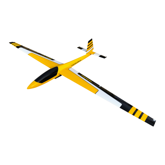
- Page 1 SWIFT S-1 SWIFT S-1 INSTRUCTION MANUAL INSTRUCTION MANUAL ART. 22000 | ART. 22001 ART. 22000 | ART. 22001 www.tomahawk-aviation.com...
-
Page 2: Hinweise Zum Umweltschutz
KONTAKT KONFORMITÄTSERKLÄRUNG Dieses Produkt entspricht den wesentlichen Schutzanforderungen gemäß den EU-Richtlinien zur elektromagnetischen Verträglichkeit. Eine Konformitätserklärung liegt vor und kann unter www.tomahawk-aviation.com Tomahawk Aviation GmbH eingesehen werden. Carl-Benz-Straße 7 89284 Pfaffenhofen a.d. Roth Deutschland www.tomahawk-aviation.com contact@tomahawk.gmbh +49 -7302 782 182... -
Page 3: Spezifikationen
DEUTSCH VORWORT Wir beglückwünschen Sie zum Erwerb der SWIFT S-1 ARF. Es handelt sich um ein vorbildähnliches Segelkunstflugzeug von hoher Qualität, welches in einem brei- ten Geschwindigkeitsbereich und für den Kunstflug eingesetzt werden kann. Die Bauausführung eines solchen Modells und damit verbundene Detaillösungen unterliegen einer gewissen Geschmacksab- hängigkeit. - Page 4 DEUTSCH MONTAGE DES RUMPFES Beginnen Sie mit dem Anpassen des Servobret- tes im Rumpf. Es sollte möglichst weit hinten vorm Steckungsrohr eingesetzt werden. Noch nicht jetzt verkleben! Schrauben Sie das Höhen- und Seitenruder- servo in die vorgesehenen Aussparungen im Servobrett. Der Hebel des Höhenruderservos sollte bis Bohrung ca.
- Page 5 DEUTSCH Optional: Um ein Aufplatzen des Rohres bei ho- hen Belastungen zu vermeiden, sollte das Rohr beidseitig mit Glasmatte verstärkt werden. Hierzu werden nach Anschleifen beide Enden mit getränkter 80g Glasmatte zweifach umwi- ckelt. Die Sperrholz Führung für das Gestänge wird mit Epoxy auf ca.
- Page 6 DEUTSCH Führen Sie nun die gleichen Schritte vorn am Servohebel durch, nachdem Sie das Seil durch die entsprechende Rumpföffnung geführt haben. Sorgen Sie für eine kleine Vorspannung beider Seile bei neutralem Ruder- und Servohorn. Dann werden auch hier die Quetschhülsen mit einer Zange verpresst. Durch weiteres Einschrauben der Augbolzen in die Gabelköpfe erhöhen Sie nun die Vorspannung der Seile.
-
Page 7: Montage Der Flächen
DEUTSCH MONTAGE DER FLÄCHEN Beginnen Sie mit dem Einbau der Querruder und Wölbklappen Servos in die Halterungen. Befestigen Sie die Servos mit den CfK Laschen und Holzschrauben. Ziehen Sie die Servokabel in die Fläche ein und verlöten Sie sie mit den Servos. - Page 8 DEUTSCH Die Länge der Querrudergestänge ergibt sich aus dem Abstand der Bohrungen bei 90° aus- gerichtetem Servoarm und dem neutralen Ru- derblatt. Die Länge der Klappengestänge ergibt sich aus dem Abstand der Bohrungen bei 90° ausgerichtetem Servoarm und ca. 15mm Ausschlag der Klappe nach unten. Sind alle diese Arbeiten abgeschlossen und die Servos und Gestänge mechanisch und elektrisch justiert, können die Servoschachtabdeckungen mit UHU Por aufklebt und die Gestänge final eingehängt werden.
- Page 9 DEUTSCH RUDERAUSSCHLÄGE Normal Landung ▲ 22 mm ▲ 15 mm Querruder ▼ 13 mm / 20%Expo ▲ 13 mm Höhenruder ▼ 10 mm / 20% Expo ▼ 3 mm Seitenruder ◄ 75 mm ► 75 mm Wölbklappen ▼ 45 mm FLUGEMPFEHLUNG Suchen Sie sich nun einen Tag mit geeignetem Wetter für den Erstflug.
-
Page 10: Instructions For Disposal
This product complies with the essential pro- tection requirements of EU directives regarding electromagnetic compatibility. A Declaration of Conformity is available and can be checked under www.tomahawk-aviation.com Tomahawk Aviation GmbH Carl-Benz-Straße 7 89284 Pfaffenhofen a.d. Roth Germany www.tomahawk-aviation.com contact@tomahawk.gmbh +49 -7302 782 182... -
Page 11: Specifications
Congratulations on your purchase of the new SWIFT S-1 ARF. The SWIFT S-1 ARF is a high-quality semi-scale aerobatic glider with a dynamic flight envelope. It can be flown within in a broad speed range and also in aerobatics. There a various ways of const- ructing the model, depending on your preferences. - Page 12 ENGLISH ASSEMBLY THE FUSELAGE Start by adjusting the servo board in the fuse- lage. It should be glued in as far back as possib- le in front of the wing joiner tube. Do not glue now! Screw the elevator and rudder servo into the slots provided in the servo board.
- Page 13 ENGLISH Optional: In order to avoid bursting of the tube under high loads, the tube should be reinforced on both sides with glass fabric. For this purpo- se, after sanding both ends are wrapped twice with soaked 80g glass mat. The plywood guide for the linkage is glued with epoxy to about half the length of the linkage between the fuselage sidewalls.
- Page 14 ENGLISH Now perform the same steps at the front of the servo lever, after you pulled the wire through the openings in the fuselage back. Provide a small preload of both ropes with neutral rudder and servo horn. Then the crimp sleeves are pressed by pliers. By further screwing the eyebolt into the clevis you now increase the tension of the cables.
- Page 15 ENGLISH ASSEMBLY THE WINGS Begin by installing the aileron and flap servos in the brackets. Attach the servos with the carbon tabs and wood screws. Pull the servo cables into the wing and solder them to the servos. To avoid subsequent rattling of the servo cables in the wing, it is advisable to provide the cable with foam pieces.
- Page 16 ENGLISH The length of the aileron linkage results from the distance of the bores at 90 ° aligned servo arm and the neutral rudder blade. The length of the flap linkage results from the distance of the bores at 90 ° aligned servo arm and about 15mm deflection of the flap down.
-
Page 17: Control Throws
ENGLISH CONTROL THROWS Normal Landing ▲ 22 mm ▲ 15 mm Ailerons ▼ 13 mm / 20%Expo ▲ 13 mm Elevator ▼ 10 mm / 20% Expo ▼ 3 mm Rudder ◄ 75 mm ► 75 mm Flaps ▼ 45 mm FLIGHT RECOMMENDATIONS Now look for a day with suitable weather conditions for the first flight. - Page 18 NOTICE / NOTIZEN...
- Page 19 NOTICE / NOTIZEN...
- Page 20 2018 | Tomahawk Aviation GmbH | Carl-Benz-Str. 7 | 89284 Pfaffenhofen | Germany...
Need help?
Do you have a question about the SWIFT S-1 and is the answer not in the manual?
Questions and answers