Table of Contents
Advertisement
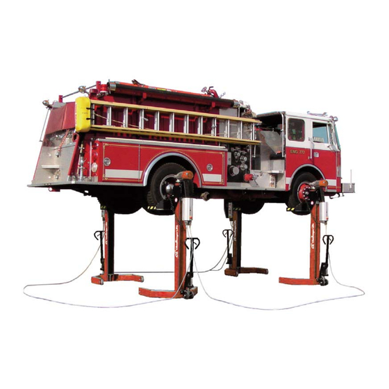
Installation, Operation & Maintenance Manual
M
C
L
OBILE
OLUMN
IFT
M
CLM16 & CLM16-W
ODELS
16,000
. C
P
C
LBS
APACITY
ER
OLUMN
200 Cabel Street, P.O. Box 3944 Louisville, Kentucky 40201-3944
Email:
Web site:
sales@challengerlifts.com
www.challengerlifts.com
/
Office 800-648-5438
502-625-0700 Fax 502-587-1933
IMPORTANT:
READ THIS MANUAL COMPLETELY BEFORE
INSTALLING or OPERATING LIFT
5/8/09
CLM16 IOM.
DOC
Advertisement
Table of Contents

Summary of Contents for Challenger Lifts CLM16-W
- Page 1 Installation, Operation & Maintenance Manual OBILE OLUMN CLM16 & CLM16-W ODELS 16,000 APACITY OLUMN 200 Cabel Street, P.O. Box 3944 Louisville, Kentucky 40201-3944 Email: Web site: sales@challengerlifts.com www.challengerlifts.com Office 800-648-5438 502-625-0700 Fax 502-587-1933 IMPORTANT: READ THIS MANUAL COMPLETELY BEFORE INSTALLING or OPERATING LIFT 5/8/09 CLM16 IOM.
- Page 2 CLM16 & CLM16-W ODELS PERATION AND AINTENANCE ANUAL Safety IMPORTANT SAFETY INSTRUCTIONS Thoroughly read all decal and manual instructions before installing, operating or maintaining the lift. They are provided to prevent personal injury and property damage. Replace any decal unreadable or missing on your lift.
- Page 3 CLM16 & CLM16-W ODELS PERATION AND AINTENANCE ANUAL Safety Instructions SAFETY INSTRUCTIONS Read operating and safety manuals before using lift. SAFETY INSTRUCTIONS Proper maintenance and inspection is necessary for safe operation. SAFETY INSTRUCTIONS Do not operate a damaged lift. SAFETY...
- Page 4 Cautions CAUTION Lift to be used by trained operator only. CAUTION Authorized personnel only in lift area. CAUTION When moving lift, be careful to avoid tipping. 5/8/09 CLM16 IOM.
- Page 5 CAUTION Check for overhead obstructions before raising vehicle. Warnings WARNING Clear area if vehicle is in danger of falling. WARNING Remain clear of lift when raising or lowering vehicle. 5/8/09 CLM16 IOM.
- Page 6 WARNING Locate lift on firm, level surface, preferably concrete. WARNING Be sure intended lifts are moving together evenly. WARNING All lifting forks must properly engage vehicle tires or supports. 5/8/09 CLM16 IOM.
- Page 7 WARNING Do not drive over or pinch electrical cables. WARNING Keep feet clear of lift while lowering. 5/8/09 CLM16 IOM.
- Page 8 WNER MPLOYER ESPONSIBILITIES Lift Operator Qualifications and Training The owner/employer shall ensure that all lift operators have the appropriate qualifications and that they are trained in the safe operation of the lift by making use of the following materials: manufacturer supplied operation &...
-
Page 9: Safety Features
Safety Features WARNING Do not use the lift with any safety devices inoperative !!! Emergency Stop Button Serves to disconnect the lift in case of emergency. Main Switch Serves to turn the lift ON and OFF. When in position 0 the switch can be padlocked (also see Lockout/Tag out Procedure in Maintenance Instructions). -
Page 10: Specifications
Specifications 5/8/09 CLM16 IOM. - Page 11 Standard Metric Rated load capacity (per column) 16,000 lbs 7,273 kg Raising / Lowering time 113 s Supply voltage 3~208/230/440/480 V, 60 Hz Control voltage 24 V Fuse protection (per column) 7 A @ 208/230V 4 A @ 440/480V Motor power 2.5 hp 1.8 kW Weight (per column)
-
Page 12: Installation
Installation Handling / Location CAUTION Make sure the columns are lifted properly by the structure and NOT by the carriage. Make sure all items in use to lift the column are rated for at least the weight shown in the specifications. Screw an eye bolt M16 into the threaded hole on top of the motor plate of the column. -
Page 13: Jumper Setting
Jumper Setting CAUTION Prior to initial operation make sure the jumpers are set correctly. Non-compliance may result in damage to motor and power supply unit !!! Power Supply Unit 208/230 V 440/480 V !!! Before opening power supply unit (MCB), ensure that it is disconnected from the Main Power Supply (Wall Outlet) !!! 1) Open the power supply unit. -
Page 14: Motor Cable
Motor 1) Remove the cover of motor junction box. 2) Verify the jumper setting corresponds to the line voltage. 3) Reinstall cover of motor junction box. Motor Cable Motor Cable For 208/230 V, three jumpers For 440/480 V, two jumpers must be set must be set vertically. -
Page 15: Operation
In case of defects or malfunctions such as jerky lift movement or deformation of the superstructure, support or lower the lift immediately !!! Turn off and lock the main switch. Contact CHALLENGER LIFTS, INC. Immediately !!! Use lift only as indicated by the supplied instructions !!! Should you have further questions, please contact CHALLENGER LIFTS, INC. - Page 16 Controls Overview Power Supply Unit Main Switch C Control Unit LED Display 2 Selector Button 3 Seven-Segment Display 4 "Raise" Button 5 "Lower" Button 6 Emergency Stop Button 7 5/8/09 CLM16 IOM.
-
Page 17: Installing The Power Supply Unit
Installing the Power Supply Unit Attach the power supply unit (P) to the left side of the control unit (C) to ensure easy access to the main switch. Main Switch The main switch can also be used as an Emergency Stop switch. Turn to position 0. Position 1: Lift is ready for operation. -
Page 18: Control Elements
Control Elements LED Display Indicates operating and error states. Selector Button (on Control Unit) Use this button to select between: Automatic mode (A) Single mode Group mode Seven-Segment Display (on Control Unit) Indicates operating and error codes. RAISE Button (on Control Unit) Press and hold this button to raise the lift. - Page 19 NOTE: Secure the connecting cable plugs using the safety clamps. After connecting all columns plug MCB into wall outlet. Recheck all electrical connections. Once the main switch is turned on, the lift is ready for operation. Connecting Cable Power Supply Unit 2 Dummy Plug Control Unit 3 Main Plug (NOT included)
- Page 20 Small Wheel Adapter Usage CAUTION Please read the following information carefully before using your lifting system Use the following tables to determine which carriage combined with which Small Wheel Adapter best fits the size tire on the vehicle you intend to lift!!! 5/8/09 CLM16 IOM.
- Page 21 SMA-2H Standard Carriage Wide Body Carriage 5/8/09 CLM16 IOM.
- Page 22 SMA-2 Standard Carriage Wide Body Carriage 5/8/09 CLM16 IOM.
-
Page 23: Single Mode
Operating Modes Automatic Mode Select "automatic mode" by pressing this button on each column. Activation of this operating mode is indicated by the letter on the seven-segment display. Use these buttons on the control unit to raise or lower the lift. Single Mode Select "single mode"... -
Page 24: Group Mode
Group Mode Select "group mode" by pressing and holding this button for approx. two seconds. Activation of this operating mode is indicated by the lit LED on the selector button and the letter 2 seconds the seven-segment display. The columns not in group mode are temporarily inoperative. This is indicated by the letter A flashing on the seven-segment display. - Page 25 Uncontrolled operation Error code appears on columns which do not communicate via CAN bus (e.g. due to bus line failure or use of wrong connecting cable). Operating yellow the lift is still possible. Synchronization control is disabled, synchronization monitoring remains active.
-
Page 26: Manual Lowering
Locking the Main Switch Use a padlock to protect the lift against unauthorized usage. In addition to locking the main switch, it is also possible to remove the End Plug from the system in order to make the lift system in operational. - Page 27 WARNING Intermittently lower the columns in increments of approx. 2" !!! Simultaneously – push the latch inward (arrow) using a long screw driver – Carefully pull the manual release lever outward (arrow). (Use extreme caution to ensure safe lowering speed!) The lowering speed will vary depending on the weight of the raised vehicle.
-
Page 28: Annual Inspection
(Lock-out / Tag-out) !!! DO NOT SERVICE THE ELECTRICAL PORTION OF THE LIFT AT ANY TIME WITHOUT PRIOR AUTHORIZATION FROM CHALLENGER LIFTS, INC. !!! PLEASE REFER TO THE MAINTENANCE INSTRUCTIONS FOR THE PROPER LOCKOUT / TAGOUT PROCEDURE !!! FOR MORE INFORMATION REFER TO THE LOCKOUT / TAGOUT PROCEDURE IN THE MAINTENANCE INSTRUCTIONS AND ANSI Z244.1... - Page 29 Moving Gear Regularly oil or grease the rollers of the moving gear. Cleaning CAUTION Caustic cleaning fluids, salt water and brake fluid attack coatings and sealing materials. Wash these substances off the lift immediately. Do not use high pressure or steam jet cleaners !!! 5/8/09 CLM16 IOM.
- Page 30 Load Capacity of Hydraulic Dolly If the dolly is not able to lift the unloaded column, adjust the hydraulic pressure. The adjusting device is located below the lifting gear (see arrow). CAUTION Adjust the load capacity in a way that the lifted dolly supports the weight of the unloaded column only.
-
Page 31: Troubleshooting
Troubleshooting Error Code / LED / Lift Behavior Possible Cause Remedy E1 / Red LED on one column, green LED on all others. / Lift has stopped. Carriage contacted obstacle while being Switch column to single mode. Raise lowered. carriage and remove obstacle. E2 / Red LED on one column. -
Page 32: Speed Measurement
Maintenance Sensors Speed Measurement Proximity switch B3 – used for speed measurement – is located in a threaded hole at the worm gear unit (1). Use the inspection hole (2) to check for correct adjustment of the proximity switch. Adjusting Proximity Switch B3: Set a clearance of 5/64"... - Page 33 Lower Limit Switch 5/8/09 CLM16 IOM.
- Page 34 Adjusting the Bottom Stop: The bottom-stop angle (1) is mounted to a rail (3) in the lower part of the column. To adjust the stopping point release the slider block clamp (2, 5) by opening the screw (4). Position the bottom-stop angle as required.
- Page 35 Safety Switch (Old Design) Note that the switch-off bracket is available in three versions. See below. 5/8/09 CLM16 IOM.
- Page 36 without Switch-off Bracket Ramp Adjust proximity switch B2 as per drawing below. with Switch-off Bracket Ramp Manually push the proximity switch to its topmost position. Then set a clearance of 5/64" (2 mm) between proximity switch and switch-off bracket. 5/8/09 CLM16 IOM.
- Page 37 Safety Switch (New Design) Set a clearance of 5/16" (8 mm) between proximity switch and switch-off angle. 5/8/09 CLM16 IOM.
- Page 38 Solenoid Switch of Safety Catch The solenoid switch (1) keeps the latch (14) in the disengaged position to prevent the wedge and counterwedge (16, 19) from engaging during normal operation. Item Description Solenoid Switch Allen Screw M4x70 DIN 912 Washer A10.5 DIN 125 Spring Washer A10 DIN 127 Hex Head Cap Screw M10x65 DIN 933 Hex Head Cap Screw M12x70 DIN 933...
-
Page 39: Lockout Procedure
Lockout Procedure ______________________________________________________________________________________ A) Purpose This procedure establishes the minimum requirements for the lockout of energy isolating devices whenever maintenance or servicing is done on machines or equipment. It shall be used to ensure that the machine or equipment is stopped, isolated from all potentially hazardous energy sources and locked out before employees perform any servicing or maintenance where the unexpected energization or start-up of the machine or equipment or release of stored energy could cause injury. - Page 40 Type(s) of stored energy - methods to dissipate or restrain. (7) Ensure that the equipment is disconnected from the energy source(s) by first checking that no personnel are exposed, then verify the isolation of the equipment by operating the push button or other normal operating control(s) or by testing to make certain the equipment will not operate.
-
Page 41: Parts Breakdown
Parts Breakdown Column Additional base frame heights available upon request !!! Column, Base Frame Height 6" 5/8/09 CLM16 IOM. - Page 42 Item Description Base Frame 6" (155 mm) Base Frame 6" (155 mm), Extended Column Switch-off Angle Mounting Rail, Asymmetrical Slider Block Clamp M6x15 Tapping Screw M5x8 Hex Nut M12, Self-Locking Screw Bearing Axle Heavy Load Wheel Shim Ring 20x28x2 Washer A13 5/8/09 CLM16 IOM.
- Page 43 Column, Base Frame Height 2" 5/8/09 CLM16 IOM.
- Page 44 Item Description Base Frame 2" (50 mm) Switch-off Angle Mounting Rail, Asymmetrical Slider Block Clamp M6x15 Tapping Screw M5x8 Setscrew M8x8 Screw Bearing Axle Roller Plain Bearing GLY.PBG 202316.5 F 5/8/09 CLM16 IOM.
-
Page 45: Column Cover
Column Cover 5/8/09 CLM16 IOM. - Page 46 Item Description Rubber Band Rubber Support Washer A8.4 Hex Head Screw M8x16 Clamping Piece Tapping Screw Ø3.5x13 5/8/09 CLM16 IOM.
- Page 47 Dolly 5/8/09 CLM16 IOM.
- Page 48 Item Description Hydraulic Lifting Gear Moving Gear Lifting Gear Support Axle Plastic Wheel Washer A21 Cotter Pin Ø5x50 Hex Head Cap Screw M8x20 Washer A8.4 Serrated Lockwasher A8.4 Hex Head Cap Screw M12x70 Hex Nut M12, Self-Locking Washer A13 Setscrew M6x12 Hex Head Cap Screw M8x12 5/8/09 CLM16 IOM.
-
Page 49: Drive Assembly
Drive Assembly 5/8/09 CLM16 IOM. - Page 50 Item Description Worm Gear Motor Hex Head Cap Screw M8x30 Washer A8.4 Dummy Plug Allen Screw M6x30 Clamping Plate Ring Clamping Element Drive Pin Feather Key A8x7x50 Castle Nut Setscrew M12x18 Deep Groove Thrust Ball Bearing 53 309 U309 Allen Screw M6x20 Top Plate Power Supply Unit Assy.
- Page 51 Carriage Standard 5/8/09 CLM16 IOM.
- Page 52 Item Description Carriage Wedge Latch Compression Spring 0.4x5x16 Dowel Pin 6x80 Counterwedge T-Nut M10 Spacer Plate 1 mm Spacer Plate 0.5 mm Spacer Plate 2 mm Solenoid with Flange Allen Screw M4x70 Hex Nut M4, Self-Locking Solenoid Support Washer A6.4 Serrated Lockwasher A6.4 Hex Head Cap Screw M6x12 Distributor Box Holder...
- Page 53 Universal 5/8/09 CLM16 IOM.
- Page 54 Item Description Carriage Wedge Latch Compression Spring 0.4x5x16 Dowel Pin 6x80 Counterwedge T-Nut M10 Spacer Plate 1 mm Spacer Plate 0.5 mm Spacer Plate 2 mm Solenoid with Flange Allen Screw M4x70 Hex Nut M4, Self-Locking Solenoid Support Washer A6.4 Serrated Lockwasher A6.4 Hex Head Cap Screw M6x12 Distributor Box Holder...
- Page 55 Item Description Support Fork Support Fork Support Fork, Left Side Support Fork, Right Side Cotter Pin 5/8/09 CLM16 IOM.
-
Page 56: Safety Switch
Safety Switch Previous Design New Design Item Description Limit Switch Bracket Proximity Switch Namur M18 Switch-off Angle Phillips Screw M4x6 Switch-off Angle Hex Head Cap Screw M6x25 Washer A8.4 Hex Nut M6, Self-Locking 5/8/09 CLM16 IOM. -
Page 57: Power Supply Unit
Power Supply Unit Item Description Switch Box Mounting Bracket Serrated Lockwasher A8.4 Hex Head Cap Screw M8x16 Hex Head Cap Screw M8x18 Hex Nut M8, Self-Locking 5/8/09 CLM16 IOM.
Need help?
Do you have a question about the CLM16-W and is the answer not in the manual?
Questions and answers