
Subscribe to Our Youtube Channel
Summary of Contents for GMC MDI 2
- Page 1 Multiple Diagnostic Interface 2 User Guide Multiple Diagnostic Interface 2 User Guide © 2015 GM Customer Care and Aftersales Made in the U.S.A. All rights reserved.
-
Page 2: Table Of Contents
Setting Up the MDI 2 Hardware ................... 16 Setting Up Wireless Communications ................20 Power On Self-Test (POST)..................22 Connecting the MDI 2 to a Vehicle ................23 Finishing Up ........................24 Troubleshooting ........................ 26 Cleaning and Maintenance ....................31 Cleaning and Storing Your MDI 2 ................ -
Page 3: Introduction
Multiple Diagnostic Interface 2 User Guide Introduction The Multiple Diagnostic Interface 2 (MDI 2) User Guide provides a quick reference and overview of the Multiple Diagnostic Interface 2 system. Everything contained in this manual is based on the latest production information available at the time of publication. -
Page 4: Customer Support Overview
Multiple Diagnostic Interface 2 User Guide Customer Support Overview To obtain assistance with your TIS software, contact the ACDelco Aftermarket Support Center. Before Calling Before making a call for ACDelco Aftermarket support, be sure to have the following information ready: ... -
Page 5: Important Pc Hardware Guidelines
Multiple Diagnostic Interface 2 User Guide Important PC Hardware Guidelines ACDelco provides IT guidelines to help users have a seamless experience when using TIS2Web software applications. To avoid unnecessary compliance issues with TIS2Web, please review and adhere to the stated infrastructure guidelines at the following link: http://www.gmdesolutions.com/services/standards.php These guidelines for GM Dealers also apply to Independent Service Centers, Professional Service Centers and Key Fleets using ACDelco Aftermarket subscriptions. -
Page 6: Symbols Used
Multiple Diagnostic Interface 2 User Guide Symbols Used Warning Notices - Structure and Meaning Warning notices warn of dangers to the user or people in the vicinity. Warning notices also indicate the consequences of the hazard as well as preventive action. Warning notices have the following structure: KEY WORD –... -
Page 7: Important User Information
However, the right is reserved to make changes at any time without notice. Before starting up, connecting and operating the MDI 2, it is absolutely essential that the operating instructions/owner’s manual and, in particular, the safety instructions are studied carefully. -
Page 8: Safety Instructions
MDI 2 Vehicle Communication Interface. This user manual is written for safe convenient setup and use of the product. We recommend that you carefully read the manual prior to using the MDI 2 and software. DANGER – High Electrical Voltage... - Page 9 The MDI 2 satisfies the requirements of the EMC directive 2004/108/EG. The MDI 2 is a class/category A product as defined by EN 55 022. The MDI 2 may cause high- frequency household interference (radio interference) so that interference suppression may be necessary.
- Page 10 Multiple Diagnostic Interface 2 User Guide WiFi Compliance This equipment complies with the following worldwide wireless standards. Safety / Environmental Compliance This equipment complies with the following worldwide safety and environmental standards.
-
Page 11: Product Description
PC System Requirements The MDI 2 Software runs on a PC/Laptop. The user interacts with the MDI 2 software for device setup, and configuration for SAE J2534 or ISO 22900 data transfer and ECU reprogramming. - Page 12 The MDI 2 Kit includes hardware and cables needed to transfer data and reprogram ECUs on vehicles through the DLC connector. The Wireless MDI 2 Kit (Bosch p/n EL-52100) US and Canada - Includes the MDI 2 assembly with two USB Wireless Adapters, DLC Cable, USB Cable, and Ethernet Cable. The Self Test Adapter is sold separately.
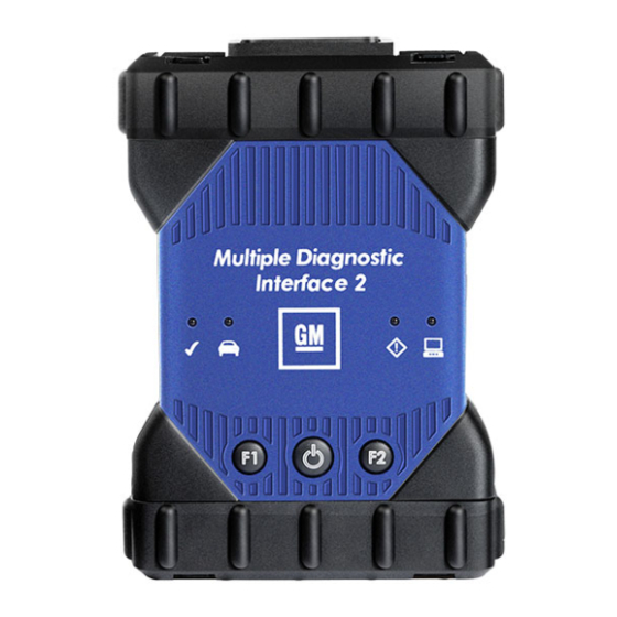
- Page 13 Multiple Diagnostic Interface 2 User Guide Item Description LED Indicators Power Button LED USB Port Type A DB26 Connector (DLC Cable) USB Port Type A USB Port Type B - PC Connection Port Wireless Adapter Ethernet Port...
- Page 14 Universal Serial Bus (USB – Item 6) The MDI 2 has a fixed USB configuration which cannot be changed. This ensures that the MDI 2 can always be connected to a single PC running the MDI Manager software so you can configure LAN or WLAN settings required by your local network.
- Page 15 Beeping may occur if the DLC is accidently dislodged. The MDI 2 may be powered over USB only to perform firmware updates from your PC. 12V power can be supplied by the vehicle DLC or the DLC Cable Self Test Adapter.
-
Page 16: Getting Started
PC. Initially you use the MDI Manager software to set up the configuration of each MDI 2. The MDI Manager is also used to update the firmware on the MDI 2. Use the following procedure to install the MDI Manager software on your PC. - Page 17 PC. Identifying Your MDI 2 The MDI 2 label is located on the back of the MDI 2. The MDI 2 identification number has two parts: a manufacturing code for traceability and a unique serial number. The serial number is used to identify the MDI 2 in the MDI Manager software.
- Page 18 Select the MDI Manager icon from the PC Desktop. Before proceeding to the next step, make sure your MDI 2 is powered on and the MDI 2 is connected to the PC using the USB cable. The MDI 2 will boot in Recovery Mode.(only in factory setup) When you click on the new MDI 2, the Connect button will change to the Recover button.
- Page 19 MDI Manager software is in control of that MDI 2. Note: If your MDI 2 is connected to another networked PC, it will still be detected by the MDI Manager but will not be available for selection. [If your MDI 2 is connected via USB to your computer, the MDI Manager functions on all tabs are available;...
-
Page 20: Setting Up Wireless Communications
MDI 2 network connection interfaces including wireless access and security settings. You must be connected to the MDI 2 via USB to access the settings on the Network Setup tab. If you are not connected via USB, the controls on the Network Setup tab are disabled. - Page 21 2. Plug the MDI 2 into external 12v power. 3. Plug the USB cable into the PC and MDI 2 and allow the MDI 2 to boot completely. 4. Select and Connect to your MDI 2 in the MDI Manager software MDI 2 Explorer tab.
-
Page 22: Power On Self-Test (Post)
USB hub. Power-on your PC. 2. Connect the MDI 2 to your PC using the USB cable and allow the MDI 2 to boot completely. Do not plug the MDI 2 USB cable into a USB hub. -
Page 23: Connecting The Mdi 2 To A Vehicle
Refer to the electrical wiring diagram for the vehicle you are testing to determine the location of the DLC on the vehicle. Connect the 26-pin end of the ETE cable to the top of the MDI 2, then tighten the screws. Connect the 16-pin end of the ETE cable to the vehicle DLC connector. -
Page 24: Finishing Up
There are two controls in this area: the Default Device control and the Auto-Connection Order control. The Default Device text box allows you to type the serial number of the MDI 2 that you want to define as your default device. - Page 25 Multiple Diagnostic Interface 2 User Guide The Default Device connection method attempts to connect to the Default Device (MDI 2) using the first available connection in the following order: USB, Ethernet, Wireless. The Device Explorer connection method opens a dialog box which shows if MDI 2s are detected.
-
Page 26: Troubleshooting
MDI 2 Vehicle LED is Blinking Red If the MDI 2 does not detect 12V on Pin 16 of the DLC cable, the MDI 2 will inform the user by automatically turning on and blinking the Vehicle LED red. This condition might be seen if the MDI 2 is only powered by a 5V USB connection or if the DLC Cable has accidently been displaced from the vehicle Data Link Connector and is powered from the backup capacitor. - Page 27 MDI 2 Speaker is Beeping If the MDI 2 is performing diagnostic services for the PC and does not detect 12V on Pin 16 of the DLC cable, the MDI 2 will inform the user of the loss of power by beeping the speaker. This condition might be seen if the DLC Cable has been removed from the vehicle Data Link Connector while the MDI 2 is still communicating with GDS2 or Tech2Win application.
- Page 28 PC Application is Unable to Communicate with the MDI 2 over USB MDI Manager Software must be installed on the PC, and the MDI 2 must be powered up before it will communicate. The MDI 2 must be configured through USB before it will communicate using any other connection types.
- Page 29 If all installed applications are unable to communicate with the MDI 2 then Connect the MDI 2 to the PC using USB but do not connect it to the vehicle, Do not connect through a USB Hub or a repeater cable.
- Page 30 Multiple Diagnostic Interface 2 User Guide If using point to point confirm the PC has a single dongle connected, connect the MDI 2 to the PC using USB Confirm the communication is enabled and the IP configuration is properly set using the MDI...
-
Page 31: Cleaning And Maintenance
Cleaning and Maintenance Cleaning and Storing Your MDI 2 The housing of the MDI 2 module may only be cleaned using a soft cloth and a neutral cleaning agent. Do not use any abrasive cleaning agent or rough cleaning cloths. - Page 32 Multiple Diagnostic Interface 2 User Guide 6. Select the latest version of the MDI 2 Recovery Image and click Start Update. Do not unplug the MDI 2 from the PC or remove power from the MDI 2 during the recovery process.
-
Page 33: Glossary
FOR CONNECTING SYSTEMS TO A NETWORK. HERTZ - A UNIT OF MEASURE FOR FREQUENCY LOCAL AREA NETWORK LIGHT EMITTING DIODE MDI MANAGER PC SOFTWARE THAT CONFIGURES, TESTS, AND UPDATES THE MDI 2 ORIGINAL EQUIPMENT MANUFACTURER PERSONAL COMPUTER POST POWER ON SELF TEST...
Need help?
Do you have a question about the MDI 2 and is the answer not in the manual?
Questions and answers