Advertisement
Quick Links
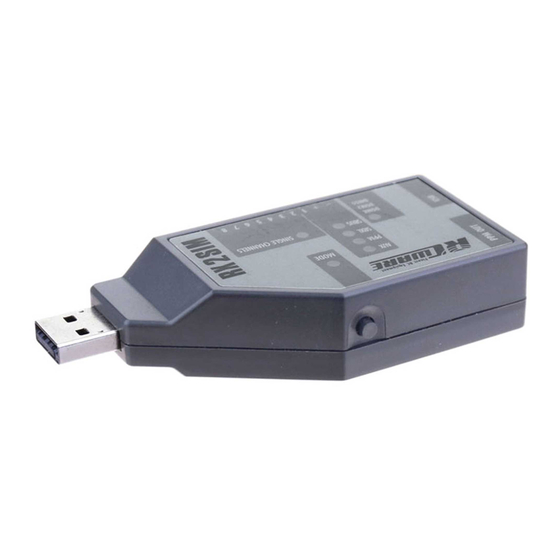
RX2SIM
RX2SIM
PPM OUT
USB
PPM OUT
USB
1 SPECIFICATION
• Operating Voltage: 3.8V – 6.0V (typical 5.0V)
• Dimensions (LxWxH): 92 x 42 x 20 mm
• Weight: 32g
1.1 CONNECTIONS
PPM-
MANUAL 1.0 ENG
Output
USB
(Dongle)
Spek trum-
Satellite
• PPM
• SRXL
• S.Bus / S.Bus2
• USB2SYS
Servo
Single Channels
Finest RC Equipment
Button
RX2SIM
RX2SIM
AUX
AUX
MODE
MODE
(Computer)
PPM
PPM
SRXL
SRXL
SBUS
Input channel
SINGLE CHANNELS
SBUS
DSM2
DSM2
DSMX
DSMX
RX2SIM
– + 1 2 3 4 5 6 7 8
– + 1 2 3 4 5 6 7 8
AUX
MODE
PPM
SRXL
SBUS
SINGLE CHANNELS
DSM2
RX2SIM
DSMX
– + 1 2 3 4 5 6 7 8
AUX
MODE
PPM
SRXL
SBUS
SINGLE CHANNELS
DSM2
DSMX
RX2SIM
– + 1 2 3 4 5 6 7 8
AUX
MODE
PPM
SRXL
SBUS
SINGLE CHANNELS
DSM2
DSMX
– + 1 2 3 4 5 6 7 8
– +C1 C2 . . . . . . . . . . . . C8
USB (Computer):
This connects RX2SIM to the computer and also supplies power to RX2SIM. Connect
RX2SIM either by plugging it into a USB socket of the PC directly or by using a stan-
dard type A USB extension cable.
If the connection is made through a USB hub, the hub should have a separate power
supply in order to avoid current overload of the PC's USB port if more than one USB
device is active at the same time.
RC Receiver:
USB
RX2SIM supports various types of RC receivers: S.Bus, S.Bus2, SRXL, combined PPM
or up to eight separate servo channels, as well as Spektrum Satellites (DSM2 and DSMX).
In general, the receiver does not need a separate power supply, as RX2SIM supplies
power to the receiver. Other devices (e.g. servos) must not be connected to the
receiver in order to avoid excessive current consumption!
PPM Output:
This connector outputs the control signals
to your simulator interface. The functionality
matches the trainer port of your RC transmitter.
USB (Dongle):
Here you can connect the USB interface or dongle of your simulator software. In
operating mode "Simulator-Dongle", RX2SIM connects this port with the computer's
USB port. In operating mode "Game Controller", this port is not active. If needed,
connect your simulator dongle to another USB port of your computer.
1.2 CONNECTING A RECEIVER WITH SEPARATE SERVO OUTPUT CHANNELS
Connect the first servo output channel from the receiver with RX2SIM via the
three-wire patch cable. This connection also supplies voltage for the receiver.
Connect channels 2 to 8 using the 7-wire patch cable. On these servo plugs only the
impulse line (orange wire) is connected.
Please refer to your receiver's manual or the imprint on its case to determine which
pin is the impulse line on each servo connector.
Ground
Signal
3,5mm phone jack, 2-pole (mono)
Advertisement

Related Manuals for RCWARE RX2SIM

Summary of Contents for RCWARE RX2SIM
- Page 1 1 SPECIFICATION This connects RX2SIM to the computer and also supplies power to RX2SIM. Connect RX2SIM either by plugging it into a USB socket of the PC directly or by using a stan- • Operating Voltage: 3.8V – 6.0V (typical 5.0V) dard type A USB extension cable.
- Page 2 PPM OUT PPM OUT PPM OUT for each servo channel) from the receiver to RX2SIM, cable from the receiver to RX2SIM, which forwards the The control signals are transmitted from the satellite which forwards the controls via USB to the computer as...
- Page 3 Initially, disconnect the satellite from RX2SIM, connect RX2SIM with the computer Please do not press the button on RX2SIM at this time in order to get into the and set Receiver Type to „Spektrum” (see section 2.2). Now connect the satellite to - The LED flashes if there is no valid RX signal detected, which, for instance, might be operational mode.
Need help?
Do you have a question about the RX2SIM and is the answer not in the manual?
Questions and answers