Table of Contents
Advertisement
Quick Links
Advertisement
Table of Contents

Summary of Contents for Micro control systems MCS-THERMOSTAT
- Page 1 Installation & Reference Guide Version 1.5 5580 Enterprise Pkwy. Fort Myers, FL 33905 MCS-THERMOSTAT Office: 239-694-0089 Fax: 239-694-0031 www.mcscontrols.com MCS Total Solution for all your Control Energy Efficient and RoHS Compliant Needs Revsion 2016-04-08...
- Page 2 Micro Control Systems, Inc. This document and the information contained herein shall be treated as proprietary. Reasonable provisions shall be provided to ensure that this information remains proprietary by your employees, agents, and other personnel that may have access to this document.Copyright ©2016...
-
Page 3: Table Of Contents
MCS-THERMOSTAT REVISION 1.5 Table of Contents MCS Thermostat’s Interface ..........................5 Thermostat’s Display .............................6 Icons Display ...............................7 Installation ................................8 4.1. REQUIRED FOR INSTALLATION ........................8 4.2. MOUNTING LOCATION ..........................8 Installation - Mounting ............................9 5.1. UTILIZING J-BOX ............................9 5.2. PUNCTURE SMALL HOLE ..........................9 5.3. - Page 4 DISPLAY TEST ............................19 12.8. ADJUST BACKLIGHT ..........................19 12.9. STANDBY BACKLIGHT ..........................19 12.10. ADJUST TIME ............................19 12.11. ADJUST DATE ............................19 12.12. THERMOSTAT RESET ..........................19 12.13. SOUND ALARM ............................19 13. Update Firmware on Thermostat ........................20 13.1. MCS-Thermostat firmware uploads ......................20 14. Troubleshoot Section ............................21...
-
Page 5: Mcs Thermostat's Interface
MCS-THERMOSTAT REVISION 1.5 MCS Thermostat’s Interface The MCS-THERMOSTAT’S interface allows the viewing of 17 different parameters and has the ability to adjust 9 settings, including cooling & heating set points, operational schedules, holiday schedules, calibration and password protection. Enter Menu... -
Page 6: Thermostat's Display
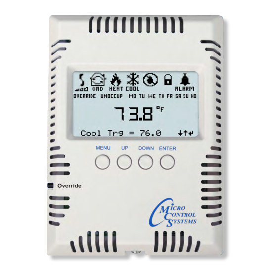
MCS-THERMOSTAT REVISION 1.5 Thermostat’s Display (Display Test) The LCD screen displays seven icons reporting operational mode, current status and alarms. Unit is in COOLING mode Unit is in DEHUMIDIFICATION Unit is in HEATING mode Indicates position Thermostat is LOCKED of outside Air Damper... -
Page 7: Icons Display
MCS-THERMOSTAT REVISION 1.5 Icons Display Unit has an active alarm. Unit is in cooling mode. Unit is in dehumidification mode. Evaporate fan is running (speed indicator low, medium, high). LOW MED HIGH Unit is in heating mode. Outside air damper is closed. -
Page 8: Installation
• The Thermostat should be mounted approximately 5’ (1.5m) above the floor. 4.3. WIRING AND DISTANCE Use 4 wire 22 to 20 awg Shielded Cable for installation. The MCS-THERMOSTAT can be installed up to 1000 feet from the MCS CONTROLLER. -
Page 9: Utilizing J-Box
5.1. UTILIZING J-BOX MCS recommends you install the MCS-THERMOSTAT utilizing a J-Box. Prior to installing the MCS-THERMOSTAT punch out the corresponding mounting holes on the MCS-THERMOSTAT housing based on the J-box you are utilizing. MCS-THERMOSTAT REVISION 1.1 MCS-THERMOSTAT REVISION 1.1 MCS-THERMOSTAT REVISION 1.1... -
Page 10: Wiring Instructions To Micromag (Rev. 6.0 Or Less)
REVISION 1.5 Wiring Instructions to MicroMag (Rev. 6.0 or less) TURN POWER OFF TO CONTROLLER AND THERMOSTAT FIRST Begin wiring (not supplied) from the MCS CONTROLLER to the MCS-THERMOSTAT as seen in the wiring diagram below. ONE THERMOSTAT PER MCS-CONTROLLER MicroMag... -
Page 11: Wiring Instructions To Micromag (Rev. 6.1 Or Greater)
REVISION 1.5 Wiring Instructions to MicroMag (Rev. 6.1 or greater) TURN POWER OFF TO CONTROLLER AND THERMOSTAT FIRST Begin wiring (not supplied) from the MCS CONTROLLER to the MCS-THERMOSTAT as seen in the wiring diagram below. ONE THERMOSTAT PER MCS-CONTROLLER (MCS) -
Page 12: Wiring Instructions To Magnum
MCS-THERMOSTAT REVISION 1.5 Wiring Instructions to MAGNUM TURN POWER OFF TO CONTROLLER AND THERMOSTAT FIRST Begin wiring (not supplied) from the MCS CONTROLLER to the MCS-THERMOSTAT as seen in the wiring diagram below. ONE THERMOSTAT PER MCS-CONTROLLER MAGNUM (MCS) I/O port... -
Page 13: Sound Alarm Stat
MCS-THERMOSTAT REVISION 1.5 Thermostat Menu Screens Use ‘UP’ ‘DOWN’ and ‘ENTER’ BUTTON TO MOVE BETWEEN SETTINGS 9.1. SETUP (APPEARS FIRST TIME THERMOSTAT IS TURNED ON) 9.1.1 Net Address (Factory Set At 1) 9.1.2 Units Degrees (F) Or (C) 9.1.3... -
Page 14: Setup (Appears First Time Thermostat Is Turned On)
MCS-THERMOSTAT REVISION 1.5 10. SETUP (APPEARS FIRST TIME THERMOSTAT IS TURNED ON) NOTE: THIS MENU WILL APPEAR THE FIRST TIME YOU Occup POWER UP THE THERMOSTAT. SETUP ADDITIONAL CHANGES CAN BE MADE USING THE CONFIG MENU AFTER THE ‘INITAL SETUP’... -
Page 15: Setup (Continued)
EXIT SETUP MENU Press ENTER to exit the SETUP menu, all changes made in the SETUP settings will be saved in the MCS-THERMOSTAT non volatile flash memory. YOUR THERMOSTAT IS SETUP AND READY FOR USE. ADDITIONAL CHANGES CAN BE MADE USING THE CONFIG MENU... -
Page 16: Main Menu Settings
MCS-THERMOSTAT REVISION 1.5 11. Main Menu Settings CLICK ON MENU TO SEE THE SCREENS BELOW AUTHORIZATION PASSWORD LEVEL MAY BE REQUIRED NOTE: SOME MENU SELECTIONS WILL NOT SHOW ON YOUR THERMOSTAT LCD SCREEN, IF THEY ARE NOT SETUP IN THE CONFIGURATION FILE FOR YOUR CONTROLLER. -
Page 17: Config Menu Settings
MCS-THERMOSTAT REVISION 1.5 12. Config Menu Settings NOTE: IF THERMOSTAT SHOWS LOCKED ICON, NO CHANGES Occup Occup CAN BE SAVED UNTIL YOU MENU BECOME AUTHORIZED MENU Config Menu Config Menu SHOWS UNLOCKED CLICK ON MENU - USE DOWN BUTTON TO SEE THE CONFIG MENU AUTHORIZATION PASSWORD MAY BE REQUIRED NOTE: SOME MENU SELECTIONS MAY NOT SHOW ON YOUR THERMOSTAT LCD SCREEN. -
Page 18: Setting Each Day Of The Week
MCS-THERMOSTAT REVISION 1.5 Config Menu (continued) 12.3.1 SETTING EACH DAY OF THE WEEK Schedule setting start with Sunday as the first day. 1. Press Menu button to ‘CONFIG MENU’, press ‘ENTER’ 2. Use ‘DOWN’ to ‘MODIFY SCHEDULES’, press ‘ENTER’... -
Page 19: Modify Holidays
Hit ‘ENTER’ - Allows user to make changes to the backlight - OFF or 25% to 100% 12.10. ADJUST TIME Allows the user to change the displayed time from the MCS-THERMOSTAT. Directions: Use the Up/Down arrows and Enter button to first adjust the hour per a 24-hour schedule (ex. -
Page 20: Update Firmware On Thermostat
MCS-THERMOSTAT REVISION 1.5 13. Update Firmware on Thermostat 13.1. MCS-Thermostat firmware upload Loading new ‘Firmware’ to the Thermostat (requires proper authorization) Consult support@mcscontrols.com for upgrading your Thermostat firmware and acquiring the necessary TERMINAL BLOCK CABLE TO ATTACH TO THERMOSTAT. REMOVE COVER FROM THERMOSTAT AND REMOVE THE WIRES FROM THE PLUS AND MINUS FOR THE COMMUNICATION OF THE THERMOSTAT. -
Page 21: Troubleshoot Section
On the communications Setup Screen select the LOCAL Comm. COM port from your computer and then set the baud rate to 38400. Press Save and click SERIAL to connect with the MCS-Thermostat. When MCS-Connect screen opens a red line will appear on the site info showing the Software information of the MCS-Thermostat. - Page 22 Terminated correct. In MCS-CONNECT or Keypad, check to see if the baud rate is WITH THE CONTROLLER correct(38,400) MCS-THERMOSTAT remains in locked mode until the proper password is entered. Press the Menu button until you see Password - press enter, than your first password THERMOSTAT IS IN LOCKED number - press enter until the correct password has been entered.
Need help?
Do you have a question about the MCS-THERMOSTAT and is the answer not in the manual?
Questions and answers