Advertisement
Quick Links
Download this manual
See also:
User Manual
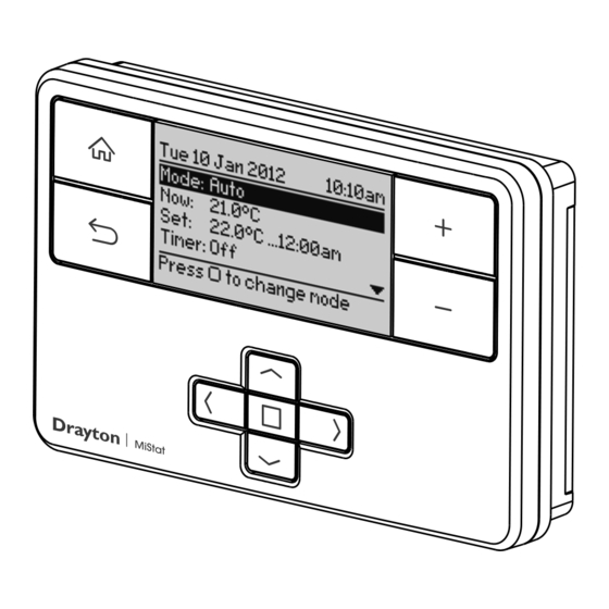
MiStat Programmable
Room Thermostat
Model: P710R
M iS ta
t
Customer Service Tel: 0845 130 5522
Customer Service Fax: 0845 130 0622
Technical Helpline: 0845 130 7722
Website: www.draytoncontrols.co.uk
E-mail: customer.care@invensys.com
@DraytonControls
l
x
/DraytonControls
EU Design Regs:- 002180638-1/2/3
Installation Guide 06490189001 Iss E
INSTALLATION Guide
Step 2: Wiring
Volt free contacts
N
L
1
2
3
230V AC 50Hz
Common
Call for
heating
heat
Fused 3A
satisfied
or call for
cooling
This product is double insulated and does not
require an earth connection. The MiStat R should
be wired to the boiler or central heating wiring
using the correct type of cable or fl ex. The MiStat
R should be wired to replace hard wired room
or programmable thermostats, as shown on the
system or boiler wiring diagrams.
Always check other manufacturers instructions for
compatibility.
Applications
The electronic room thermostat MiStat P can be used
for temperature control together with:
•
Boilers
•
Oil and gas warm water heating
•
Actuators of fl oor heating systems or radiators
•
Circulating pumps
•
Heat pumps
A MiStat R receiver is required for operation.
Note: To ensure a properly working heating
system, the menu items in the Installer settings
have to be set according to the needs of the
heating system, see step 5.
Caution!
The radio receiver may be installed only by a competent
electrician in compliance with the circuit diagram
enclosed in the top housing cover or in compliance
with these instructions. The current safety regulations
must be observed.
In order to achieve protection class II, adequate
installation measures must be taken.
This radio receiver, which can be installed separately,
is designed exclusively for temperature control in dry
and closed rooms and standard environments. This
electronic device was created according EN60730-1, it
operates according working principle 1C.
Combi boiler basic wiring layout
Switched
Switched
230V AC
230V AC
L -
L -
fused 3A,
fused 3A,
N -
N -
N
L
1
2
N
L
1
2
MiStat R
MiStat R
Zone control basic wiring layout
Switched live
Switched live
from wiring
from wiring
centre
centre
230V AC
230V AC
fused 3A
fused 3A
N
L
1
2
N
L
1
2
MiStat R
MiStat R
Step 1: Mounting the Wall-plate
! IMPORTANT:
Installation must only be carried out by a
qualifi ed electrician or heating engineer.
Make sure mains input has a 3 amp fuse.
! CAUTION! Before installation, make sure the
mains supply is switched off!
! DO NOT
use a surface
mounting box
Internal
Internal
boiler
boiler
electronics
electronics
External
External
controls
controls
connections
connections
3
3
Radio signals
Radio signals
to MiStat R - no wiring
to MiStat R - no wiring
Motorised valve
Motorised valve
N
N
To boiler
L
To boiler
L
and/or
and/or
pump
pump
3
3
Radio signals
Radio signals
to MiStat R - no wiring
to MiStat R - no wiring
Client
Invensys
Artworker
-
Creative Director
Mike Lane
Modification Date
20/04/15 11:59AM
Option 1: Fitting a new wall-plate
The ideal location is close to the boiler or central
heating system. For the best performance install
in an open space, at least 30cm distance from any
metal objects including wall boxes and the boiler
housing. It is recommended that the MiStat R is
mounted on the wall nearest the fi nal location of
the MiStat P room unit and not less than 30cm
from the boiler side panel.
Loosen the securing screws, remove the wallplate
and, if surface wiring is to be used, snap out
the cable entry strip on the bottom edge of the
wallplate with a pair of pliers. Fix the wallplate,
terminals at the top, either direct onto the fl at
wall using wall plugs and no 6 x1" wood screws
or on a plastic fl ush mounting single conduit box
using M3.5 x 14 screws. Check that there's 20mm
clearance to the right of the wall-plate and 25mm
above it. Complete the wiring to the MiStat R
wallplate in accordance with the wiring diagram
in step 2, to comply with current IEE regulations.
Place the MiStat R onto the wallplate and tighten
the securing screws.
Check the 3A fuse, and switch on the mains.
Warning: Installing the MiStat R too close to the
metal side panel or mains cables may interfere
with the radio signal.
Option 2: Using an existing wall-plate
Loosen the securing screws on the old receiver
and unplug it. Check that there's 20mm
clearance to the right of the wall-plate and 25mm
above it. Check the wiring diagram for your
product model to compare terminals and, if
necessary, change the wiring of the wall-plate to
suit. Now plug the MiStat R unit into the
wall-plate and tighten the securing screws.
Check the 3A fuse, and switch on the mains.
Step 3: Signal Strength
The MiStat Programmable Room thermostat is pre-
bound to the MiStat receiver in the factory so they just
need to be positioned in the best place for wireless
communication.
To help with this there is a built in Signal strength
indicator as shown below (see also Step 5 Installer
settings).
It is recommended that the signal strength is 'Good'
or 'Very Good' to ensure ongoing communication
is maintained.
If 'Poor' is displayed, look for a better location.
If 'No Signal' is displayed, try connecting again with
the room unit in a different position.
Note: If not bound, the bind screen will be visible.
For commissioning see Step 6
File Name
7378 Drayton Instruction Manual Update 06490189001
Finished Size
280x297mm
PRINT
Artwork %
100%
Proof Stage
Bleed
3mm
Advertisement

Subscribe to Our Youtube Channel
Related Manuals for Drayton P710R


Summary of Contents for Drayton P710R
-
Page 1: Room Thermostat
MiStat R Radio signals MiStat R to MiStat R - no wiring to MiStat R - no wiring Client Invensys File Name 7378 Drayton Instruction Manual Update 06490189001 Artworker Finished Size 280x297mm PRINT Creative Director Mike Lane Artwork % 100%... -
Page 2: Technical Data
Enter the Installer telephone number if required Set password Set password to restrict access to the Service settings 0000 Client Invensys File Name 7378 Drayton Instruction Manual Update 06490189001 Artworker Finished Size 280x297mm PRINT Creative Director Mike Lane Artwork %...
Need help?
Do you have a question about the P710R and is the answer not in the manual?
Questions and answers