Table of Contents
Advertisement
Quick Links
Soldering Hints
1
Put leads through mounting holes from the side with
part outline. Ensue component evenly touch PCB.
2
Solder leads at the other side. Solder should fully
fill and cover soldering pads.
Avoid bridges between
neighbering pads.
Cut unused leads
3
flush with cutter.
Step 1
Assembly Main Board and LCD board (follow the order as numbered)
1. Resistors
Note:
Always meter resistor
values before soldering
R7, R36
:
180Ω
R1, R14, R16 100KΩ
:
R8, R12, R13 120Ω
:
R2
1.8MΩ
:
R9, R15, R26 1KΩ
:
R3
200KΩ
:
R10
3KΩ
:
R4
:
2MΩ
R11, R38
:
1.5KΩ
R5
:
20KΩ
R28, R40
:
470Ω
R6
300Ω
:
R37, R39
:
10KΩ
2. HF-Chokes
L1,L3,L4
:
100 H
μ
3. Diodes
Cathode
D1
:
1N5819
D2
:
1N4004
(or 1N4007)
4. Crystal
Y1
8MHz
:
JYE Tech Ltd.
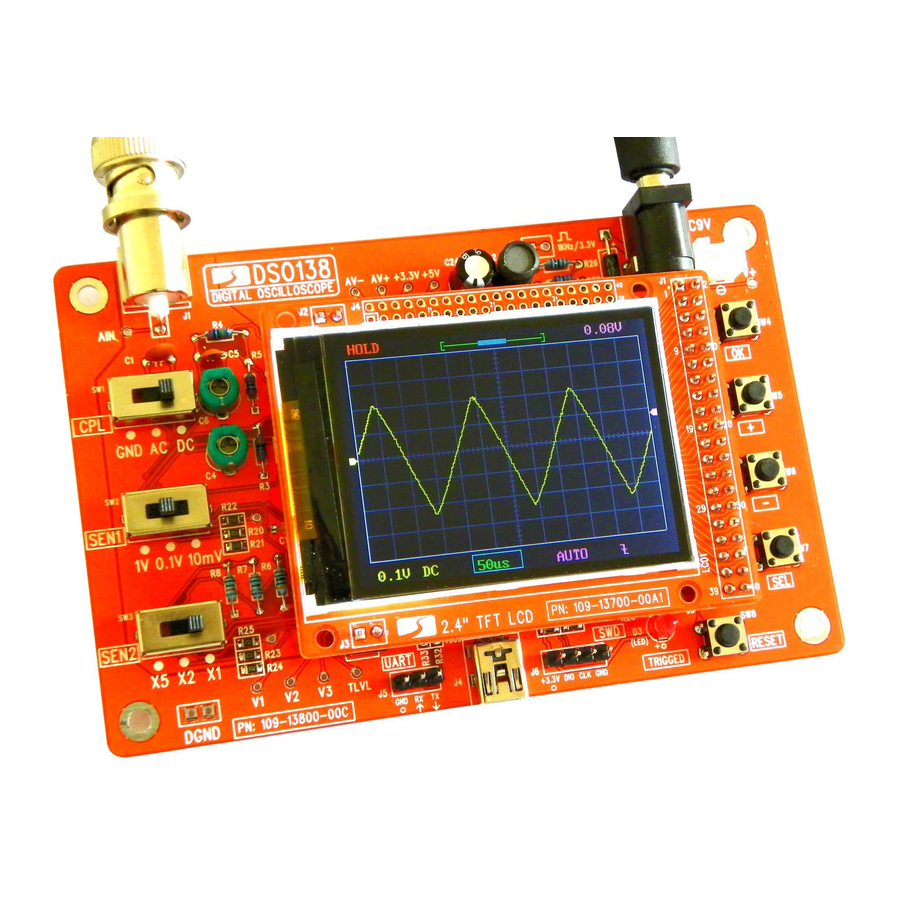
- www.jyetech.com -
DSO 138 Oscilloscope DIY Kit
User Manual
Tools you need
1
4
Screw driver
Iron (20W)
2
Solder wire
5
Flush cutter
Tweezers
3
Multimeter
6
5. USB Socket *
J4
USB mini -B
:
6. Tact Switches
SW4, SW5,
:
6 X 6 X 5mm
SW6, SW7,
SW8
7. Ceramic Capacitors
C1, C9,
:
μ
0.1 F
C10, C11,
C14, C15,
C16, C17,
C18, C20,
C23
C7, C8
C2
:
330pF
:
120pF
C3
3pF
:
C12, C13
:
22pF
C5
:
1pF
8. LED
Solder positive pole
(the longer lead) to
D3
:
φ3mm, green
the square pad
Rev. 01
Before you start
1
Check part values & quantities against part list
2
Always meter resistor values before soldering
3
Understand all part polarities and orientations
* These parts are optional and not required
for the normal oscilloscope function.
9. Pin header (for power)
Face the opening
outward
2 Pin
J9
:
10. Transistors
Q1
:
8550
Q2
:
9014
11. Regulators
:
79L05
U4
U5
:
78L05
12. Capacitor trimmers
C4, C6
:
13. Power inductor
L2
1mH/0.5A
:
14. Electrolytic capacitors
Solder positive pole
C19, C21,
(the longer lead) to
C22, C24,
the square pad
C25, C26
15. Power connector
16. Pin-header (male) *
J5
17. Pin-header (female)
J7, J8
J3
18. Slide switches
SW1, SW2,
SW3
5 - 30pF
19. BNC connector
:
100 μ /1 6V
F
:
DC005
J10
:
1 X 3 pin
J6
:
1 X 4 pin
:
1 X 2 pin
:
2 X 20 pin
2P3T
:
J1
BNC
:
Page 1
Advertisement
Table of Contents

Summary of Contents for DIY DSO 138
- Page 1 Soldering Hints DSO 138 Oscilloscope DIY Kit 14. Electrolytic capacitors User Manual Put leads through mounting holes from the side with part outline. Ensue component evenly touch PCB. Rev. 01 Solder leads at the other side. Solder should fully Tools you need Before you start fill and cover soldering pads.
-
Page 2: Troubleshooting
20. Test signal ring 21. JP3 22. LCD Board Note: Install to the side 1 ) Make a small ring with a Short JP3 with solder lead cut-off. opposite to LCD panel. 2 ) Solder the ring to the two 2 X 20 pin holes of J2 (as shown in the photo). - Page 3 How to Use Probe Calibration Leave black clip Connect red clip to Because there is always some capacitance between scope input and un-connected test signal output Display and Controls ground probe needs to be calibrated to achieve better measurement results for high frequency signals. This can be done with the help of Trigger Level the built-in test signal.
Need help?
Do you have a question about the DSO 138 and is the answer not in the manual?
Questions and answers