Table of Contents
Advertisement
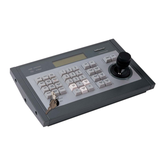
V2117 Series
System Keyboard
Installation/Operation Instructions
This manual applies to products:
V2117/V2117X
This manual describes the installation and operation procedures of V2117 series system keyboards.
Compatible with the matrix switching systems, digital video recorders (DVRs) and network video recorders
(NVRs) of the company, V2117 series system keyboards are capable of handling video switching, system
setup, menu programming, pan/tilt and lens control, alarm acknowledgement, salvo switching and DVR/NVR
control.
V2117 series system keyboards can establish Ethernet or bi-directional RS-232 communications with the
matrix switching systems of the company. Six different baud rates are provided to meet various requirements.
They also feature built-in RS485 and Manchester control code generators for direct control over 16 site
receivers and super domes. Besides, they could directly control DVR through RS-485 interface and NVR
through network interface.
To facilitate system operation, the LCD display window indicates site number, camera number, monitor
number, as well as any digital inputs from the keyboards.
Advertisement
Table of Contents

Summary of Contents for Infinova V2117X
- Page 1 System Keyboard Installation/Operation Instructions This manual applies to products: V2117/V2117X This manual describes the installation and operation procedures of V2117 series system keyboards. Compatible with the matrix switching systems, digital video recorders (DVRs) and network video recorders (NVRs) of the company, V2117 series system keyboards are capable of handling video switching, system setup, menu programming, pan/tilt and lens control, alarm acknowledgement, salvo switching and DVR/NVR control.
- Page 3 This manual may not be reproduced in any form or by any means to create any derivative such as translation, transformation, or adaptation without the prior written permission of Infinova. Infinova reserves the right to change this manual and the specifications without prior notice. The most recent product specifications and user documentation for all Infinova products are available on our website www.infinova.com.
- Page 4 Read this manual carefully before installation. This manual should be saved for future use. Important Safety Instructions and Warnings Electronic devices must be kept away from water, fire or high magnetic radiation. Clean with a dry cloth. Provide adequate ventilation. ...
-
Page 5: Table Of Contents
Table of Contents 3.2 Matrix System Setup ............10 Chapter I General Description ............. 1 1.1 Description ................1 3.2.1 System Reset ............... 11 1.2 Models .................. 1 3.2.2 Arranging Monitor Display ......... 11 1.3 Features ................. 1 3.2.3 Programming Monitor Tour ........11 1.4 Keyboard Layout .............. -
Page 7: Chapter I General Description
There is a user login feature for added system security. RS485 and Power Manchester Infinova Ethernet Manchester code outputs allow for direct control over Infinova RS485 SYSTEM KEYBOARD series receivers/drivers or dome cameras. Meanwhile, they could AUXILIARY CONTROL... -
Page 8: Chapter Ii Keyboard Setup And Installation
4800 9600 Note: In order to facilitate system connection, please use the 19200 connection accessories provided by Infinova. To ensure normal 38400 operation and desired functions, please perform the following setup procedures on your keyboard prior to system operation or Example: If the desired baud rate is 4800, first press ACK to select programming. -
Page 9: Rs485 Setup
There are two options in the “Joystick Setup” menu. To set the Set to: current original position for the joystick, just press the NEXT or Infinova protocol (Default baud rate at 4800) LAST key to toggle between below two options: Pelco-P protocol (Default baud rate at 9600) Samsung protocol (Default baud rate at 4800) “Zero Position”... -
Page 10: Beeper Setup
There are two options in the “RPT Setup” menu. connections in this chapter. Unless noted otherwise, the descriptions To toggle between the following two options using the NEXT or illustrated by V2117 apply to V2117X as well. LAST key: “ON”=to select the PTZ Control Mode for Infinova matrix... -
Page 11: V2117 Keyboard Controls Receivers/Drivers
PQRS WXYZ NEAR SHOT PATRN PROG PRST UNIT SHIFT ZOOM communications with Infinova series matrix switching systems OPERATE CLEAR WIDE TELE PROGRAM DOWN MENU (V2011, V2015, V2020, V2040, and V2060). Here is just an V2117 example to show RS-232 communications with V2011 matrix Figure 2-3. -
Page 12: Ethernet Communications
V2117 V2117 Figure 2-8. System Connections Using a Port Expander V2117 keyboard can establish Ethernet communication with most Infinova series matrix switching systems. Here is just an example to show Ethernet connections with V2015 matrix switching system. VIDEO INPUTS ALARMS... -
Page 13: Chapter Iii Keyboard Operation And Programming
Chapter III Keyboard Operation and SITE Programming 0089 This chapter describes the operation and programming procedures for a matrix switching system. Please make sure that V2117 At 8-digit camera number display mode, the LCD will display as keyboard has been correctly connected to the matrix switching follows: system prior to operation or programming. -
Page 14: Establishing Ethernet Communication
3.1.2 Establishing Ethernet Communication To establish the communication between V2117 keyboard and At 12-digit camera number display mode, the LCD will display as Infinova series matrix switcher/controller systems via Ethernet follows: network, simply route the Ethernet port on the rear panel of V2117 via Hub to the Ethernet port on the matrix switching system. -
Page 15: Video Switching
Camera switching is achieved by first calling a monitor to a times. Infinova series matrix switching systems support two types of keyboard and then calling desired cameras to that monitor. -
Page 16: Calling A Preset
An auxiliary is a relay that can be used to switch devices, such as function (i.e. pan, tilt, focus, zoom, iris) on the held camera. lights and door locks. Each Infinova series site receiver/driver or dome camera provides two auxiliary relay outputs, respectively To control a tour on hold labeled as "AUX1"... -
Page 17: System Reset
3.2.1 System Reset Press the HOLD key to hold a currently running monitor tour. While the monitor tour is in hold status, press the NEXT key to System reset refers to the procedure of resetting the matrix display the next video input in the pre-programmed sequence, and switching system currently under control to factory defaults. -
Page 18: Setting Date Format
"1 CAM" (Sets Camera 1 as the first camera input in the tour 3.2.6 Programming Preset sequence.) Infinova series receivers and Super Domes feature a preset function, "1 PROG" (Sets the Dwell Time for Camera 1 as one second.) which is programmable via the SHOT button on the keyboard. -
Page 19: Menu Programming
3.3 Menu Programming 4.1.1 Access System Setup Mode Infinova series matrix switching systems provide powerful menu-driven programming, featuring system tours, salvos, event Place the key switch in the MENU position, press F1 key, and the timers, access controls and alarm handlings. -
Page 20: System Connection
Please refer to the corresponding DVR manuals and appendix III for details on the specific meanings and operation methods of the keys. 4.4 Control DVR via Ethernet The keyboard is capable of controlling DVR via Ethernet. And the connection is shown below: Infinova POWER MANCHESTER RS485 ETHERNET... -
Page 21: Keyboard Menu Setup
“@Y”. 5.2 System Connection Please refer to section 4.3 for details about system operations. Here we take a V2117 keyboard and Infinova V3072-32K as examples to describe the connection. Note: Please refer to V2415 Manual for details about V2415 Use a network cable to connect the network interface of the configurations. -
Page 22: System Operation
NVR is not under “PTZ” status. Note: The device NO. here should be identical with that in the controlled NVR. Take Infinova V3072-32K as example. The device NO. is the ID at the path, the figure of which is shown as below, i.e. -
Page 23: Appendix I Specifications
Appendix I Specifications Appendix II Keyboard Operation under Different Protocols General Communication Protocol: RS-232, Ethernet 1. PELCO P/D PROTOCOL Matrix/Dome Output: Manchester/RS-485 Camera ID under PELCO P protocol is 1~255; and Camera ID RS-232 Selectable Baud Rate: 1200, 2400, 4800, 9600, 19200, under PELCO D protocol is 1~254. - Page 24 SUB MENU SET PATTERN 1 PROGRAM 1+PATRN EXIT THE 67+SHOT 70+SHOT MENU RUN PATTERN 1 OPERATE 1+PATRN 4. INFINOVA PROTOCOL 71+SHOT SET PATTERN 2 PROGRAM The controlled camera ID is 1~255. 2+PATRN 71+SHOT FUNCTION RUN PATTERN 2 OPERATE KEYSWITCH 2+PATRN...
- Page 25 Note: To clear or repeat a pattern, it is necessary to select the 5. MANCHESTER PROTOCOL The controlled camera ID is 1~64, and can set/call up 64 presets. corresponding pattern number after pressing 69+SHOT. PATTERN KEYSWITCH FUNCTION KEYS KEYSWITCH FUNCTION KEYS 70+SHOT SET PATTERN 1 PROGRAM...
-
Page 26: Appendix Iii Table For Functions Of Dvr Front Panel Keys
Appendix III Table for Functions of DVR Front Panel Keys Name of Keys Type Descriptions [SHIFT] Auxiliary Key Work with numeric keys to switch channels or input information [F1] Reserved temporarily (1) Used to switch from preview interface to menu operation interface. [MENU] Function Key (2) Turn off the “Ting”... -
Page 27: Appendix Iv Table For Functions Of Nvr Front Panel Keys
Appendix IV Table for Functions of NVR Front Panel Keys NVR front-panel keys operate in either PTZ mode or non-PTZ mode, which are described respectively as below. Non-PTZ Mode Keyboard Key NVR Function Under “Number” input mode, input “0”; Under multi-image tour mode, quickly call Chanel-10 image and display it in single-image mode. Under “Number”... - Page 28 Non-PTZ Mode Keyboard Key NVR Function Under non-PTZ status, switch among multiple images when previewing them. [FAR/ Note: Divide the screen into 1/4/9/16 screens, but into 8 screens. Joystick Up Select upwards within a control. Joystick Down Select downwards within a control. Joystick Left Select leftwards within a control.
- Page 29 PTZ Mode Keyboard Key NVR Function 94+ [SHOT/PRST] (PROG position) Under PTZ mode, set/save autopan 4. 94+ [SHOT/PRST] (OPER position) Under PTZ mode, call autopan 4. 71+ [SHOT/PRST] (PROG position) Under PTZ mode, set/save pattern 2. 71+ [SHOT/PRST] (OPER position) Under PTZ mode, call pattern 2.
-
Page 30: Appendix V Cable Diameter Calculation And Lightning & Surge Protection
Appendix V Cable Diameter Calculation and Lightning & Surge Protection Relation between 24VAC Cable Diameter and Transmission Distance In general, the maximum allowable voltage loss rate is 10% for AC-powered devices. The table below shows the relationship between transmission power and maximum transmission distance under a certain specified cable diameter, on condition that the 24VAC voltage loss rate is below 10%. - Page 31 Lightning & Surge Protection The product adopts multi-level anti-lightning and anti-surge technology integrated with gas discharge tube, power resistor and TVS tube. The powerful lightning and surge protection barrier effectively avoids product damage caused by various pulse signals with power below 4kV, including instantaneous lightning, surge and static. However, for complicated outdoor environment, refer to instruction below for lightning and surge protection: The product features with dedicated earth wire, which must be firmly grounded.
- Page 32 Infinova 51 Stouts Lane, Monmouth Junction, NJ 08852, U.S.A. Tel: 1-888-685-2002 (USA only) 1-732-355-9100 Fax: 1-732-355-9101 sales@infinova.com V2.6 1609...
Need help?
Do you have a question about the V2117X and is the answer not in the manual?
Questions and answers