Table of Contents
Advertisement
Quick Links
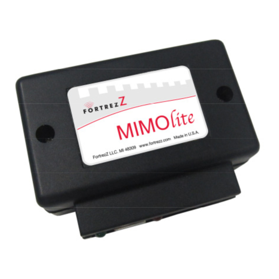
MIMOlite, Multiple Input – Multiple Output
Wireless Interface/Bridge Module, User Manual
Introduction
The MIMOlite Module is an interface / bridge module, capable of converting a wired or wireless input to a wired or wireless output. The MIMO
TM
is a Z-Wave
Wireless device compatible with other Z-Wave
Specifications
Power:
Frequency Range:
Distance Range:
Enclosure Size (L x W x D):
Weight:
Operating Temperature:
Input Signal 1 (SIG1):
Input Signal Impedance
Output Relay 1:
System Requirement:
Overview
The MIMOlite module provides one analog or digital input and one relay output (isolated dry contacts, NO-COM-NC) and can be controlled by Z-
TM
Wave
. The system includes a program switch for Z-Wave
Input SIG1 is an analog input, internally pulled-up to the MIMOlite supply voltage. The system allows trigger conditions to be set based on the
input voltage being inside or outside a user-defined range (configured via Z-Wave). This provides great flexibility for capturing events in a wide
variety of applications. The trigger status of the input can be read via Z-Wave
the Controller. In addition, a count of the trigger events that have occurred for the input channel is internally recorded (and stored in the 'pulse
count') and is available to be requested or automatically sent via Z-Wave. The current triggered/un-triggered status can also be read via Z-
Wave. The SIG1 input can be associated with up to two other Z-Wave
off) based on the occurrence of a trigger event. Finally, the analog input channel can be configured so that the analog input level (not just binary
trigger status) is periodically sent to up to two other associated nodes.
The output relay is typically commanded via Z-Wave
mapped to the output relay. For example, Relay 1 can be automatically turned on based on Input SIG1 being triggered. The relay activation can
be set via a jumper or via Z-Wave
Warnings and Precautions
* The dry contact relays are not capable of supporting higher-than-specified loads. Exceeding the specified switching power will cause damage to
the unit and may cause damage to property and/or personal injury, including loss-of-life.
* WARNING – Do not attempt to use the relays to switch residential or industrial Alternating Current (AC) lines. The relays are to be
used for low-power load control only. Refer to above electrical specifications for relays.
* Do not store highly flammable items such as oily rags or other combustibles near your MIMOlite.
* Do not apply electrical power to the unit unless the unit is fully assembled.
* Install unit in accordance with electrical codes and regulations. In case you are unsure about any parts of these instructions consult an
TM
electrician or Z-Wave
home automation specialist.
* Disconnect power source before working on or servicing the unit. Failure to do so could result in personal injury.
* WARNING - The MIMOlite must not be used in life support and / or safety applications.
TM
12-16 VDC @~ 300mA
908.4MHz (US); 868.4MHz (EU)
Max 100ft line of sight in unobstructed environment
3 3/8" (85mm) x 2 1/2" (64mm) x 1 1/4" (30mm)
4 oz (100 gram)
-10⁰C (14F) to +70⁰C (158F)
Digital or Analog Input, 0 to 16V DC, 16 Hz Max for pulse counting (min. 32
ms high or low time). The trigger levels and hysteresis can be set via the Configuration Command Class. The
input can be a dry contact closure (see open/shorted characteristics in Technical Appendix).
Input impedance for SIG1 is Z=66 ohm at 10KHz. This impedance is = 66 ohm = 34 ohm + j 540uH.
SPDT, Max. Switching power of 120W; 10uA to 10A; High Dielectric strength coil-contacts: 1,000 VAC;
Open contacts: 750 VAC; Conforms to FCC Part 68 requirements; Ag + Au clad bifurcated contacts fully sealed.
TM
Any Z-Wave
-enabled network and controller.
TM
inclusion/exclusion and a status light (LED) for various indications.
TM
commands. In addition, the user can configure the input SIG1 trigger condition to be
TM
for either momentary or latched operation - see Installation section.
1080 Centre Rd. Ste C
Auburn Hills, MI 48326
certified products. MIMOlite comes in a plastic enclosure for indoor use only.
TM
and/or can be automatically sent to a configured node, typically
TM
devices, such that an associated device will automatically turn on (or
www.fortrezz.com
Phone: (248) 481-7092
sales@fortrezz.com
Made in USA
050515
Advertisement
Table of Contents

Summary of Contents for FortrezZ MIMOlite
-
Page 1: Specifications
Wireless Interface/Bridge Module, User Manual Introduction The MIMOlite Module is an interface / bridge module, capable of converting a wired or wireless input to a wired or wireless output. The MIMO is a Z-Wave Wireless device compatible with other Z-Wave certified products. - Page 2 EXCLUSION from (removing from) a network: 1) Set up the exclusion mode at the controller (for detailed directions, please refer to your controller user manual); 2) Press the MIMOlite button and the controller will indicate the unit has been removed from the network. The Status LED will blink when the exclusion completes.
-
Page 3: Troubleshooting
Output Configuration The MIMOlite can be configured to automatically turn the relay on when the input is triggered or a Z-Wave command can also turn the relay on. The Configuration Command Class, Parameter 3, is used to set the input-to-relay mapping (See Technical Appendix). -
Page 4: Limited Warranty
MIMOlite, or the MIMOlite does not perform as expected we encourage you to return the MIMOlite to your DISTRIBUTOR for an exchange or for a full refund within 30 days of purchase. Or, you can return the MIMOlite to FORTREZZ with an RGA number.

Need help?
Do you have a question about the MIMOlite and is the answer not in the manual?
Questions and answers